Continue to Site

Welcome to our site!

Electro Tech is an online community (with over 170,000 members) who enjoy talking about and building electronic circuits, projects and gadgets. To participate you need to register. Registration is free. Click here to register now.

  • Welcome to our site! Electro Tech is an online community (with over 170,000 members) who enjoy talking about and building electronic circuits, projects and gadgets. To participate you need to register. Registration is free. Click here to register now.

1.5 Volt Tracking Transmitter

Status
Not open for further replies.

ElectroMaster

Administrator
The current draw for this tracker is 3.7mA, so the 1.5V button cell will last awhile. What the heck am I suppose to hear you ask? When your circuit is working you should see the LED flash quite fast. Take your FM radio and search for the low-beat 'humbe-humbe-humbe-etc' equal to the flash of the LED (probably around the 100Mhz). Found it? If that position is interferering with a radio station you can fine-tune it with the variable capacitor. If you like to have the tracker around the 88Mhz you can do that by spreading the windings from the home-made coil just a bit (1/2 a millimeter or so). Anyways, play with it and learn. It is a nice project. The 12-inch antenna can be anything, it is not really that critical. I used a piece of 22 gauge flexible wire. I haven't checked the range but will do that shortly.
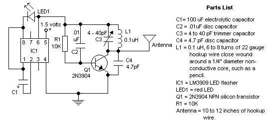
  • For stability, use a NPO types for C2 & C4.
  • Resistance tolerance for R1 should be 1 or 2%.
  • Frequency range is the usual 87-109Mhz on the FM dial.
  • The coil is made from 22 ga 'hookup' wire, like the solid Bell phone wire. Leave the insulation on.
  • The LED is the 'High Brightness' type for maximum illumination.

1.5_volt_tracking_transmitter.gif
 
I know that this is a newb question, but what is the coil(L1) for. I see it on pretty much every FM transmitter, and wonder every time, but I finally decided to ask.
 
nos_slived said:
I know that this is a newb question, but what is the coil(L1) for. I see it on pretty much every FM transmitter, and wonder every time, but I finally decided to ask.

It forms a tuned circuit, along with the variable capacitor across it. This is what determines it's operational frequency - it's a vital component in radios!.
 
I just dont understand why that circuit works like that. I still think that the output of the IC should be connected to the base of the transistor instead of where I think the +ve supply should be connected.
 
mstechca said:
I just dont understand why that circuit works like that. I still think that the output of the IC should be connected to the base of the transistor instead of where I think the +ve supply should be connected.

It simply turns the power ON and OFF to the transmitter.
 
The obsolete IC also boosts the 1.0V to 1.5V of the battery to 2V to 3V so the LED will light and the transmitter gets enough supply voltage.
 
does anyone know the distance tis can send the signal?
 
Of course its range depends on the sensistivity of the radio but I would think 30m would be its limit if it works.
I don't see how it can work without an emitter resistor of at least 100 ohms. The positive feedback capacitor C4 now feeds ground instead of feeding its signal into the emitter.
The LM3909 hasn't been made for years so might be very difficult to find.
 
well i have a lot of old devices and i probably could find the IC but i wouldnt know where to begin, do you have any ideas on what kind of appliances would have this chip and if so what would be written on the top of it?

(you can probably guess that i am a bit of a noob and dont know much more then the names of the components and what some of them do)
 
andrew12345678 said:
well i have a lot of old devices and i probably could find the IC but i wouldnt know where to begin, do you have any ideas on what kind of appliances would have this chip and if so what would be written on the top of it?

It's VERY unlikely you will find that IC in an appliance you have, I've never seen it used in anything!.
 
Years ago I saw a flashlight (torch?) that used the LM3909 IC. It was originally a 2-cell flashlight, but they removed one cell and replaced it with the LM3909 blinker/battery-voltage-boosting IC and an LED. The blinking LED was so you could find the flashlight in the dark. With only one cell, the flashlight wasn't very powerful since the LM3909 couldn't double the voltage for the lightbulb.

Google LM3909 and you will find some circuits that use a few transistors to replace the LM3909. :lol:
 
help about the receiver

guys

i need help, can anyone suggest a circuit for the receiver, instead of using a usual fm radio???? help pls
 
audioguru said:
I don't see how it can work without an emitter resistor of at least 100 ohms. The positive feedback capacitor C4 now feeds ground instead of feeding its signal into the emitter.
I know this is an old thread that has been resurrected, but I started thinking about this point. Ground has almost no meaning in this circuit. I suspect there is enough resistance (inside the chip) between pins 4 and 6 to allow the feedback to work.
 
At 100MHz, the 2N3904 or 2N2222 only has a gain of about 3. Therefore it needs a pretty big feedback signal to oscillate. The voltage divider of the capacitor or its internal capacitance to ground resistance would give a very low positive feedback signal.
 
audioguru said:
At 100MHz, the 2N3904 or 2N2222 only has a gain of about 3. Therefore it needs a pretty big feedback signal to oscillate. The voltage divider of the capacitor or its internal capacitance to ground resistance would give a very low positive feedback signal.
Ground means nothing to the oscillator. It's just a reference point from which to measure voltages. What matters is the impedance between pins 4 and 6. I simulated it, and it even oscillates in the simulation, which has zero ground resistance.
 
rovnex said:
newbie here!
i would like to ask how can i make that L1 or coil inductance?
The parts list tells how to make the coil. 6 to 8 turns of insulated hookup #22 wire around a pencil with the turns tight together. Carefully slide out the pencil and admire your coil.
 
Status
Not open for further replies.

Latest threads

Back
Top