ElectroMaster
Administrator
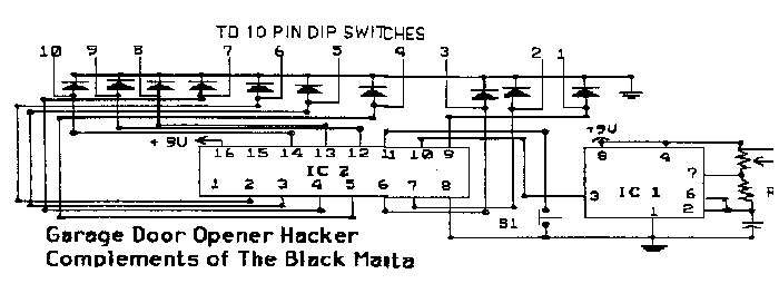
This is the instructions and schematic for a garage door hacker. It modifies an existing door opener to run through every possible code.
The garage door hacker uses a 555 timer as a pulse generator to transmit pulses to a binary counter. Each pulse will increment the binary counter by one. You can adjust the speed of the counting by turning R1. Go ahead and experiment to find just the right speed to use. Switch one is for resetting the count back to the beginning.
As you may notice, the schematics don't show how to connect directly to the garage door opener. What I do is this: First you must desolder the DIP switches from the door opener and solder an IC socket into where the DIP switches were. (This will allow you to put the DIP switches back, when operating in normal mode.) Second, you should connect the output to a wirewrap IC socket. If you mount the IC socket on your pc or perfboard you can use the socket to plug right in to the door opener. When connecting the output, be sure that the connections on the wirewrap socket correspond to the ON setting of the DIP switches.
Parts List
Resistors
R1 - PC mount 100k potentiometer
R2 - 1k ohm 1/4 watt
Capacitors
C1 - 22MFD
Integrated Circuits
IC1 - 555CP Timer
IC2 - CD4040BE 12 stage binary counter
Misc
LED1 - 10 Light Emitting Diodes
S1 - Normally Closed Momentary Push Button Switch
Perfboard
9V Battery
Additional Assembly Hints
You should have 12 leads coming from the circut when it is completed - 10 from the binary counter and 2 for power, + and -.
The 10 from the counter should go where the DIP switch was; there will be an empty socket where it was removed (obviously). One row of holes will be shorted together and go to ground, and in the other row each hole will connect individually to a pin of a nearby IC chip. Connect the 10 leads from your circut to the holes that go to the IC chip, not the ones that are shorted together.
That leaves the positive and ground leads from your circut still hanging around, just connect them to an external 9v battery or the one already used by the door opener. When connecting the positive lead to the battery, insert a 65 ohm resistor (R3 - not shown in schematic or on parts list) in series between the two - this cuts the operating voltage to about 6v, reducing the operating temperature and prolonging the life of the circut.
The most important modification of the original plans is to substitute a 20k ohm potentiometer for R1 instead of using a 100k ohm. This gives much better control over the speed at wich the circut cycles through codes.
Also, in place of using 10 individual LEDs in the circut, Radio Shack's got a nice little 10-segment LED bargraph display that makes things look a lot neater (cat. 276-081)

