3 divided by 1 is 3, so it is the square root of 3 times 100 or about 173.2 Newton meters
1 divided by 3 is 1/3 and 1/3 times 100 is 33.3, so it is about 33.3 Newton meters
The torque actually triples so it is 300 Newton meters
The torque actually doubles so it's 200 Newton meters
| Q2: For two lossless transformers both with voltage ratios equal to 1 are wired with primaries in parallel and secondaries in series and are driven by a voltage source with internal impedance of 20 ohms. What is the output impedance across the two secondaries: There are two transformers, so it adds up to 40 ohms) There are two transformers that act the same so it is still 20 ohms There are two transformers that act together, so it has to be 80 ohms There are two transformers with primaries in parallel, so it has to be 10 ohms | ||||||||||||||||||||||||
| Q2: Marking= | ||||||||||||||||||||||||
| Q3: The following equation represents a sine wave: E=Vpk*sin(w*t+Theta) What does Theta represent? E=Vpk*sin(w*t+Theta) The starting time of the sine wave The phase shift of the sine wave The angular frequency of the sine wave The peak amplitude of the sine wave | |||||||||||||||||||||
| Q3: Marking= | |||||||||||||||||||||
| Q4: The formula for the 3db cutoff frequency of a low pass filter made from a resistor R in series with a capacitor C and driven by an AC voltage source and taking the output from the junction of the resistor and capacitor to ground is: F=1/(2*pi*R*C) Using a resistor value of 1k, find the capacitor value that causes a 3db cut in the gain at a frequency F of 1 kHz. Approximate the capacitor value to three significant decimal places. C=0.159uf C=0.165uf C=0.136uf C=0.192uf | ||||||||||||||||||
| Q4: Marking= | ||||||||||||||||||
| Q5: A perfect square wave varies in amplitude between +1 volts and -1 volts. The harmonics present in this wave are: The fundamental, plus portions of all the odd harmonics No fundamental, but still includes portions of all of the odd harmonics The fundamental, plus portions of all the even harmonics No fundamental, but still includes portions of all of the even harmonics | |||||||||||||||
| Q5: Marking= | |||||||||||||||
| Q6: In a liquid crystal display, the internal light source initially gets polarized but in order to obtain the brighter light levels something else is done to the light next. What happens to the light next: It gets deflected up or down or left or right for the brighter light levels It gets twisted for the brighter light levels It gets unpolarized for the brighter levels It gets electrically boosted forward for the brighter light levels, and pushed backward for the lower light levels | ||||||||||||
| Q6: Marking= | ||||||||||||
| Q7: In an AC circuit, a coupling capacitor can help to pass the AC component of the current but block the DC component. The reason this can work is because: In an AC circuit the capacitor acts more like a resistor The capacitors ability to impede the flow of AC current is less than its ability to impede the flow of DC current The AC component gets shunted to +Vcc The DC component gets radiated into free space | |||||||||
| Q7: Marking= | |||||||||
| Q8: If we had an extremely large collection of 1000 ohm resistors (billions) where any one value could vary anywhere from plus 10 percent to minus 10 percent and we chose at random 100 of them and connected all 100 together in parallel, what would be the approximate tolerance of the resulting 10 ohm resistor: There are 100 of them so the the tolerance would be terrible, over 100 percent It doesnt matter how many there are it would still be 10 percent It would be about 1 percent because 1000 divided by 10 is 100 and 1/100 is 0.01 which is 1 percent The tolerance gets much more precise, about 0.1 percent | ||||||
| Q8: Marking= | ||||||
Q9:
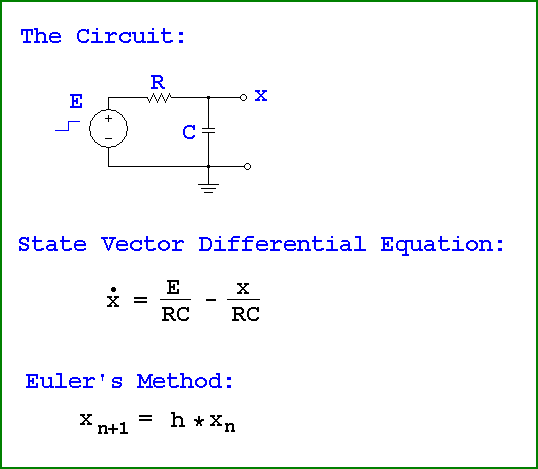
We have a resistor in series with a capacitor driven by an input step voltage E and taking the output (referenced to ground) from the junction of the capacitor and resistor. The state vector differential equation for this circuit is: x' = E/RC-x/RC (see diagram) where x is the state variable, x' is the time derivative of the state variable, E is the input voltage, RC is the product of the resistor value times the capacitor value. Euler's Method is a technique for solving this equation numerically, and is given by: x[n+1]=x[n]+h*x'[n] (see diagram) where x[n] is the current value of the state variable, x[n+1] is the next solution for the state variable, x'[n] is the time derivative calculated at n, h is the time increment. With R=1k and C=100uf and with the initial state x=0 and using a time increment of 1 millisecond, calculate the value of x (the capacitor voltage) at the time t=10 milliseconds using Euler's Method where E is the unit step forcing function, and approximate the solution to 3 significant decimal places. The value of x (the capacitor voltage) at t=10ms is: 10.5e-3 volts 8.62e-3 volts 10.4e-3 volts 95.6e-3 volts | |||
| Q9: Marking= | |||
Q10:
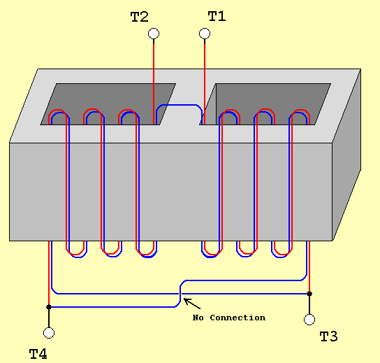
In the drawing for the transformer, each winding has the same number of turns and is wound on a lossless core as shown. If the input terminals T1 and T2 are driven with a source with internal impedance equal to 100 ohms, what is the impedance looking into the terminals T3 and T4: 400 ohms, the impedance quadriples 50 ohms, the impedance halves 25 ohms, the impedance is reduced by one quarter Close to 0 ohms, the blue wire connects between the two red wires and shorts out the primary | |
| Q10: Marking= | |