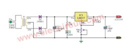
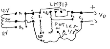
Hi, I'm a complete newbie in electronics so please bear with me. I came across this diagram online. I tried to build the circuit and made some slight changes on the values of some of the components. The changes made are the following:
• Transformer || 15V to 12V - 1 Amp
• Diode 1 & 2 || 1N4001 to 1N5004
• C2 || 10uf to 0.1uf
• All capacitors are change into 50V rating
• POT || 5k ohms to 1k ohms
I tried to simulate it on multisim before testing the actual circuit and changed the power rating of the POT into 1/8 and it turned out okay with an output of 1.25V to 11.7V. Although when I tried the circuit on actual, the POT smoked almost immediately when I turned the circuit on.
Please help me on this, I want to learn and determine the problem. I'll try again after I get some suggestions and solutions.
P.S. I checked the connections on my PCB and nothing are connected wrong. I think the problem lies around the regulator or the POT...