Continue to Site

Welcome to our site!

Electro Tech is an online community (with over 170,000 members) who enjoy talking about and building electronic circuits, projects and gadgets. To participate you need to register. Registration is free. Click here to register now.

  • Welcome to our site! Electro Tech is an online community (with over 170,000 members) who enjoy talking about and building electronic circuits, projects and gadgets. To participate you need to register. Registration is free. Click here to register now.

12V turn table home position circuit using hall effect needed

Status
Not open for further replies.

scaecrow

New Member
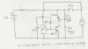
Hello folks - Looking to build a 12v turn table circuit that will allow the turn table to go to home position after power is turned off. S1 provides power to the motor, S2 (controlled by the hall effect) is in parallel. When S1 is turned off, power should still be applied to the circuit to keep the motor turning until the hall effect says that it has reached the home position. Switch S2 will then turn off. I am hoping that S2 can be a transistor not a relay. DC motor has brushes and will draw 10-15 amps.
Any help would be appreciated.
Thankx in advance
Glenn
 
No schematic yet due to new sign-up?
 
You're right - new kid on the block

Mike, Thankx for your reply. Hopefully I can figure out how to insert a bmp file before morning. Can't figure out how to change my user name either - should be scarecrow instaed (!).
Think of windshield wipers. When you turn them off (S1), S2 will still power the motor (12V) cause it's in parallel with S1. When the wipers hit bottom (home position) a magnet will tell Mr. Hall Effect to turn on which will drop its pin 3 to grnd (I think). This will turn off S2 to open the circuit. I found a 15 amp transistor - t0-3 - for S2. I know where I want to be (I think), but don't know how to get there - haven't mastered circuit design.
If you can help, that would be awesome!
Thankx again,
Glenn
 
Unlike the windshield wiper example, which has a normally closed contact for ~330 degrees of rotation, your hall effect only is "closed" while the magnet is aligned (a few degrees), you will need to invert the hall signal...
 
Diagram

Mike, Had to change it to a gif. This a crude diagram - without the inverter ...
 

Attachments

  • hall effect.GIF
    hall effect.GIF
    3.5 KB · Views: 176
You will need a 12VDC automotive type relay capable of switching 10A. Pushing S1 pulls in the relay, powers the motor, the Hall Effect, and turns on the 2n2222 such that if S1 is opened, the transistor keeps the relay pulled in. When the magnet trips the Hall Effect switch, it turns on, diverting the base current away from the 2N2222, turn it off, which allows the relay to drop out, removing power from the Hall/Transistor so that you dont need a secondary power switch. The snubber diode is required, as is the cap across the Hall Effect. See here for a typical Hall Effect Switch.

btw- use a PNG for posting drawings.
 

Attachments

  • Melexis.png
    Melexis.png
    381.1 KB · Views: 252
Thankx!

Much appreciated! I was trying to get away fom using a relay, but this will work fine!

Thank you!
Glenn
 
Status
Not open for further replies.

New Articles From Microcontroller Tips

Back
Top