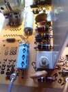
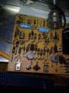
Greetings : I am fixing up a old record player. Got all the mechanical devices working properly. When played it sounds great but the tone would degrade after a few minutes. I Found a transistor (2N6124) was getting very hot and it's sister (2N6121) was warmer than the other channel after powering up for a couple minutes. I have attached the schematic and the transistors overheating are Q-11 and Q-12 at the output end. I see no blown caps or other visual signs something is wrong. I plan on replacing the electrolytics but am wondering if anyone can suggest other possibilities. The last picture has the heat sinks removed. Finally, that dark matter on the corner of the board is odd but appears to be nothing (?)
Thanks everyone. Standing by.
George
Thanks everyone. Standing by.
George
 It relies entirely on an excessively high output crystal cartridge.