Continue to Site

Welcome to our site!

Electro Tech is an online community (with over 170,000 members) who enjoy talking about and building electronic circuits, projects and gadgets. To participate you need to register. Registration is free. Click here to register now.

  • Welcome to our site! Electro Tech is an online community (with over 170,000 members) who enjoy talking about and building electronic circuits, projects and gadgets. To participate you need to register. Registration is free. Click here to register now.

2.5 watt bipolar Triangular Wave Oscillator

Status
Not open for further replies.

Farnarkler

New Member
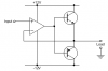
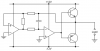
Hi guys. I am looking at building a triangular wave generator whose output will swing between +8.3 volts and - 8.3 volts driving 500Ma into an inductive 4 ohm load at around 1 hertz currently coupled through a 10 ohm 5 watt current limiting resistor. Vcc+ and Vcc minus will be +-12 volts. I think I can cobble together a oscillator using a dual TL082 jfet op amps but it would need an output stage and that is where I am a tad lost.

Any suggestions on how to approach this task would be greatly appreciated.
 
Try this. It might distort a little at higher frequencies, but 1Hz will be fine. Make sure you choose reasonably beefy transistors, because each will dissipate up to about 2W peak, 1W average, for a resistive load. If your load is very inductive this could be higher.

The op-amp is going to have to supply 10mA or so of current to the transistor bases, so it's going to get a little warm also! The TL082 might struggle a bit to supply that - if so, make the two transistors darlington types, to reduce the load on the opamp.

If you omit the feedback from the transistors' emitters, what you have is effectively a power op-amp, the output being the transistor emitters, and the inputs being the usual inverting and non-inverting inputs of the op-amp. It has a lot of cross-over distortion, but negative feedback will correct this. So, you'll probably be able to replace an op-amp in your waveform generator circuit with this circuit. The second circuit is a triangle wave generator with the integrating op-amp powered up in this way.

EDIT: Messed up circuit two - corrected and reposted
 

Attachments

  • driver.png
    driver.png
    3 KB · Views: 291
  • wave+driver.png
    wave+driver.png
    3.2 KB · Views: 381
Last edited:
Thank you so much. The second circuit looks ideal. Any recomendation on transistor selection? The load is inductive but I figured at this low frequency it should not be a problem.
 
Status
Not open for further replies.

Latest threads

New Articles From Microcontroller Tips

Back
Top