Hello, I am currently making a 3-band equalizer for part of my college project and it seems ive hit a wall.
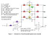
Here is the circuit on Multisim:
**broken link removed**
I have run a bode plotter and frequencies through the circuit and everything seems to work fine (oscilliscope + bode showing amplified frequencies from changes to potentiometers). After this i exported the circuit and printed up a circuit board.
After populating the PCB to the circuit diagram i tried testing the circuit for real and unfortunatly it seems to do nothing now . when changing the potentiometers, no change can be heard what so ever to music or frequencies, although it does pass the signal through
is there any visible or common mistakes in the circuit or that i could have made building the board ?
Many thanks,
Jon