Continue to Site

Welcome to our site!

Electro Tech is an online community (with over 170,000 members) who enjoy talking about and building electronic circuits, projects and gadgets. To participate you need to register. Registration is free. Click here to register now.

  • Welcome to our site! Electro Tech is an online community (with over 170,000 members) who enjoy talking about and building electronic circuits, projects and gadgets. To participate you need to register. Registration is free. Click here to register now.

3 phase star measurement

Status
Not open for further replies.

andy257

Member
Hi All,

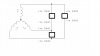
I want to measure the back EMF of a 3 phase motor in star formation. Just by turning the motor shaft by hand i should be able to measure 3 voltages (one for each phase) and see their relationship. The problem is i am not sure how to connect the GND of my DAQ.

I want to use a differential measurment for each phase.

can anyone help.

thanks
 
I am not sure where you are going with this? If this is a standard AC 3 phase motor powered by either star or delta 3 phase power and you manually rotate the motor shaft I don't think you will see anything sans a magnetic field in the motor. Exactly what is this motor?

Anytime you plan to measure 3 phase power your DAQ must allow for an isolated differential input as there is no common ground when measuring the line voltage. When measuring three phase voltage the line voltage is any phase to another phase as in A-B, B-C and C-A. The phase voltage is any phase measured to common. So the phase voltage is any phase to neutral and that can be done with a single ended input DAQ while the line voltage is phase to phase and requires a DAQ having a differential input or really bad things can happen. :)

The relationship of the phases will be 120 degree spacing. I guess I just don't quite understand what you are asking.

Ron
 
Hi Ron,

Perhaps more info was required on my part. As you say i want to measure between phases (AB, BC, CA). I have a daq card with 8 differential inputs. All i was asking was how should they be connected to meausre the voltage between the three phases.

It looks like i am going to have to connect the +ve of one channel to the -ve of another. As you also pointed out, it can go horibbly wrong if you connect it up the wrong way. I am so used to making single ended connections i am nervous about using differential.

The motor itself is just three coils of wire connected in star formation (stator) with a magnetic rotor down the middle. There are no drive electronics, its just a teaching aid motor.

Thanks
 
Last edited:
First, understand the problem.

From your description I make the following assumptions:

1 This is a 3 phase motor which is completely disconnected from its normal supply.

2 You want to turn the shaft by hand and measure the voltages generated at the motor terminals.

3 To measure these voltages you have a "DAQ" (some kind of data acquisition system), which presumably has three measurement channels.

4 Each DAQ channel has two wires for connecting to the device under test.

5 The channels are completely isolated from each other and the chassis of the DAQ.


If my assumptions are correct, the measurement system should be connected as:
One wire from each channel to a motor line terminal.
One wire from each channel to the motor windings star point.
The GND can connect to the motor casing.

JimB
 
Deleted double post
 
Last edited:
Hi Jim,

You have summed it up perfectly except i dont have access to the star point.
 
Last edited:
If you don't have access to the star point then just arbitrarily use the junction of two of the windings for the ground point. Then connect the three inputs across the three windings. (I assume the maximum voltage output of the motor is below the common-mode maximum rating of your DAQ inputs. :confused:)
 
do you mean like this?
 

Attachments

  • motor.jpg
    motor.jpg
    62.7 KB · Views: 122
I would do it like this in the attachment.

That would give a better display of the phase sequence (I think).

JimB
 
I would do it exactly as Jim B suggest. That is how I monitor 3 phase Delta using a DAQ system.

Ron
 
would you use bias resistors to prevent the signals going outside the common mode range?
 
Bias resistors? Do you mean a voltage divider? When I look at 3 phase voltages I use a DAQ with adequate voltage range. Not sure what you are asking, do you have a link to the DAQ device you plan to use?

Ron
 
Status
Not open for further replies.

New Articles From Microcontroller Tips

Back
Top