Electro Tech is an online community (with over 170,000 members) who enjoy talking about and building electronic circuits, projects and gadgets. To participate you need to register. Registration is free. Click here to register now.
Welcome to our site! Electro Tech is an online community (with over 170,000 members) who enjoy talking about and building electronic circuits, projects and gadgets. To participate you need to register. Registration is free. Click here to register now.
Hi
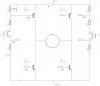
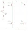
I am trying to make this h bridge and need to have 3 values of resistors. The 3 resistors works like 2 voltage dividers but I am not sure how to get the correct values. VCC is 3v and I need them to be divided into 2,3v and 0,7v
I cant have a 0,7v across r1? Like some kinda 2,3v over r2 and r3 together.
there has not yet been anyone that have been able to help me build a working h-bridge. This suggestion came from my teacher....
I cant have a 0,7v across r1? Like some kinda 2,3v over r2 and r3 together.
there has not yet been anyone that have been able to help me build a working h-bridge. This suggestion came from my teacher....
hi Simon,
If you post a diagram of the complete bridge circuit, do not add the resistor values, just draw the components as you think the circuit should be, in that way we can follow what you are trying to do.
Transistors have current inputs, not voltage inputs. If the input voltage is high enough for a high enough base current then the transistor sets its own input voltage.
use 10k ohms from base to emitter to turn off the transistor quickly and use a base current that is 1/10th the collector current for a low saturation voltage.
but with a PNP transistor the voltage from collector to base is -0.7v tus making the base voltage on the collector atleast 0.7v higher than the base and therefore I cant lead a voltage to the base that is the same as the collector.
but with a PNP transistor the voltage from collector to base is -0.7V thus making the base voltage on the collector at least 0.7v higher than the base and therefore I cant lead a voltage to the base that is the same as the collector.
No.
The base voltage of a transistor is from its base to its emitter, not from its base to its collector.
An NPN transistor usually has its emitter at 0V then it conducts current from its collector to its emitter when its base voltage is 0.6V to 1V (depending on how much current).
A PNP transistor usually has its emitter at the positive supply voltage and it conducts current from its collector to its emitter when its base voltage is 0.6V to 1V (depending on how much current) less than the positive supply voltage.
This site uses cookies to help personalise content, tailor your experience and to keep you logged in if you register.
By continuing to use this site, you are consenting to our use of cookies.

")