Electro Tech is an online community (with over 170,000 members) who enjoy talking about and building electronic circuits, projects and gadgets. To participate you need to register. Registration is free. Click here to register now.
Welcome to our site! Electro Tech is an online community (with over 170,000 members) who enjoy talking about and building electronic circuits, projects and gadgets. To participate you need to register. Registration is free. Click here to register now.
I don't think it's too specific, as long as the capacitance is not too small and the equivelant series resistance of the capacitor is not too small it will be fine. Pretty much any capacitor you use should be okay (just don't go for a super small one or a high quality low ESR one).
One diagram I found used 100uF on the input and 0.1uF on the output, while another used 0.33uF on the input and 10uF on the output.
The datrasheet shows a 0.1uF capacitor on the output and recommends a 0.22uF on the input of a 78xx regulator if it is far from the main filter capacitor.
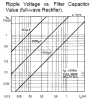
Here is a chart showing how much p-p ripple voltage there is with certain main filter capacitor values and load current:
If the Cin refers to the bulk filter capacitor that is intended to follow a 50 or 60 Hz rectifier then you might want to put some effort into estimating the size of Cin. If it is just the smaller capacitor that might be intended to reduce transients then I'd follow the manufacturer's datasheets, in the absence of better information.
If you are concerned about reducing the ripple or hum from an AC source you might consider that some of the 3 terminal regulators do suppress ripple. Paul Scherz "Practical Electronics for Inventors" has a page or two on this in a relatively easy to understand way. Electrolytic capacitors cost money and take up space - so an overly large capacitor might not be a good solution. If you do know something about the goal (ripple) then some design effort might result in a smaller but equally effective capacitor selection.
Steve, I'm sure you know this, but others may not... ALL regulators reduce ripple, some better than others. If they didn't, they wouldn't be regulators.
With a 500mA output and an 8V or more input, a 7805 will typically reduce 120Hz ripple 78dB which is a voltage ratio of 1/8,000. So 1V of ripple from the rectifier and main filter cap will be reduced to only 0.13mV.
Ron - thanks for giving me the credit though that wasn't on my mind when I replied. What I know for sure is that I don't know if the ripple reduction characteristics of many or all 3 terminal IC regulators are controlled or predictable. I am not saying that a non-predictable characteristic is of no value - just that if it isn't controlled, at least at some min or max value, then it's hard to include in design.
For DSA66 benefit - if we are talking about the big filter capacitor, note that a high degree of precision in calculations isn't a must. The bigger capacitors have quite the wide tolerance and if the calculation is important you might want to use the lowest value of capacitance expected. Now, if you have capacitors on hand that are much larger in value then within limits, use them. Less ripple is usually not a problem. At some point the current demand to charge a large capacitor can momentarily overload the circuit supplying it but that's also manageable.
This site uses cookies to help personalise content, tailor your experience and to keep you logged in if you register.
By continuing to use this site, you are consenting to our use of cookies.