Hi All,
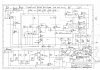
I am having trouble! I have a circuit diagram for a 300V DC, 20-500µs pulser, used to drive an inductive load (which is a solenoid gas valve, 75 Ohm resistance, situated in a vacuum chamber).
Basically, the circuit should allow you to pulse a voltage 0-300V DC over a pulse width of 20-500µs, which will drive a solenoid valve to allow gas into a vacuum chamber for experiments.
We have tried here in vain to build it, however things have gone awry, and we think that the "FET" section shown in the top right hand portion of the attached schematic is not correct.
If anyone has an idea about why, then I would greatly appreciate it.
Many thanks
DrDunk
P.S. Please ignore the various doodleings on the diagram, this is us playing around..