Hi,
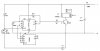
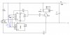
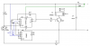
Refer to the attached schematic (a snippet of the entire circuit) - This is basically a relay driven momentary switch that just toggles ! - Really simple.. The 100R and 47uf provide a bit of protection against power spikes etc. This circuit forms part of an automotive accessory.
MY PROBLEM IS!
The unit operates from the acc power supply in the vehicle. But when the acc is turned on, the state of the switch is totally random ! - sometimes on, others off ..
Can anyone suggest a modification or something that will ensure it is always off when power is applied ???
Thanks in advance
KD