capasistor
New Member
I have built a simple sequencer circuit using a CMOS 4017 using a 9V DC wall wart power source. It works great, but I would like to have another separate sequencer circuit to be coordinated using the same clock pulse, preferably from an external pulse (a clock pulse from an external 555 in astable configuration).
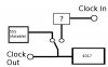
I have tried this before with external clock pulses, but I have run into a problem: if the clock pulse voltage is too low, the 4017 will not advance to the next step in the sequence. In the diagram that I attached, what additional circuit/component (labeled '?')would I need to keep the incoming voltage at an acceptable level for the CMOS 4017?
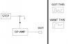
Also, the output from the sequencer goes to an op amp and outputs a square-wave-like voltage. It seems as though it mirrors the 50% duty cycle of the clock pulse. I would like the output to transition immediately from one step to the next without falling back down to zero. Is this a clock, step, or op amp issue? check out my second diagram for a visual representation of the problem.
Any advice or pointing to relevant info is appreciated. BTW this is my new favorite electronics site. You guys are wells of awesome info!!!
I have tried this before with external clock pulses, but I have run into a problem: if the clock pulse voltage is too low, the 4017 will not advance to the next step in the sequence. In the diagram that I attached, what additional circuit/component (labeled '?')would I need to keep the incoming voltage at an acceptable level for the CMOS 4017?
Also, the output from the sequencer goes to an op amp and outputs a square-wave-like voltage. It seems as though it mirrors the 50% duty cycle of the clock pulse. I would like the output to transition immediately from one step to the next without falling back down to zero. Is this a clock, step, or op amp issue? check out my second diagram for a visual representation of the problem.
Any advice or pointing to relevant info is appreciated. BTW this is my new favorite electronics site. You guys are wells of awesome info!!!