Continue to Site

Welcome to our site!

Electro Tech is an online community (with over 170,000 members) who enjoy talking about and building electronic circuits, projects and gadgets. To participate you need to register. Registration is free. Click here to register now.

  • Welcome to our site! Electro Tech is an online community (with over 170,000 members) who enjoy talking about and building electronic circuits, projects and gadgets. To participate you need to register. Registration is free. Click here to register now.

555 Timer Servo Control with Push Button and Auto Return

mactonight

New Member
Hi everyone,
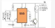
I'm working on a servo motor control circuit using a 555 timer. I have the following circuit (attach the schematic if possible). When I remove the button connected to the 68k resistor, the servo moves to 180° but does not return to 0°.

What I want to achieve:

  • When I press the button once, the servo should move to 180°.
  • It should stay in that position for 1-2 seconds.
  • Then, it should automatically return to 0° without pressing the button again.
  • I cannot use an Arduino, so I need a fully analog solution.
How can I achieve this using a 555 timer or additional components? Should I use a monostable, bistable, or another approach?
Any suggestions would be greatly appreciated.

Thanks in advance!
 

Attachments

  • WhatsApp Görsel 2025-03-12 saat 23.22.42_0abeb77b.jpg
    WhatsApp Görsel 2025-03-12 saat 23.22.42_0abeb77b.jpg
    22.9 KB · Views: 43
With no button pressed the 555 doesn't work, there's no timing resistor - you need to add a resistor between pins 7 and 6 to set the return point. However, it won't hold for 2 seconds (only while you hold the key down), you would need an extra 555, and extra complications to make it timed.

Presumably this is a school project?, hence not using a micro-controller which is the far more obvious and simpler solution.
i'm an intern student and yes this is like kinda homework and i cant use microcontroller
 
You could use a dual 555, press of button triggers one to set a D flip flop, and
triggers the second 2 sec 555. It in turn after 2 sec resets the flip flop.

Then use another 555 (ugh) to get the servo 2 mS waveform to position the
servo.

1742402760087.png


Partsy to say the least. A single ATTINY85 8 pin micro, which is a collection of analog
and logic, like a 555 is as well.

If the prof wants to you to use old school why not vacuum tubes, or magamps.....
or relay logic or.....dont ask him that....:)

You could use the tiny, and pot it after coding so it cant be seen........hide it in a brown paper bag.....
 
Last edited:
If the prof wants to you to use old school why not vacuum tubes, or magamps.....
or relay logic or.....dont ask him that....:)
Because it teaches someone how to think. The greatest skill.
 
@OP, so logically you have to generate 2 time sequences, the 2 sec on/off sequence,
and the 2 mS servo control sequence with 2 pulse width settings for the 0 and 180
angle control.

The former 555 timer(s) would do.

The latter a counter and decoding on the output to get the pulse width......
So you have to decide on resolution/degree accuracy counter must have, hence
its bit width and than calc its clock rate. Then decide on decoding to "shape"
the counter output period into correct pulse widths, 2 needed.

Thats the basics......You can use discrete 74HC logic or a CPLD to implement.....
 
So I see two references for angle. Do you agree to down view clockwise -90 to +90 as 0 to 180 ?

If so then left to right delay 1~2s and right to left , ok ?
state #)
0) idle
1) press button (leading edge , sampled state or release?) causes 1 ms high then low ,
2) 1000 ms low (minimum, 2000 ms max.) delay
3) 2 ms high (return servo) then low.
4) then back to state 0) (idle)

How about no 555 using an CR pulse out of an inverter to enable a 1kHz Osc/1024 counter IC then another CR delay to inverter ? or 3 RC one shots ? or .... fill in the blank_____________
 
It can be done with...
  • one transistor,
  • one diode
  • one 555 timer
  • one switch
(plus resistors and capacitors).
 
I have never had to use a 555 timer in all my designs with timers. But if you must, you may. Just be sure to specify which one and define your tolerances before you start. Or add the electrical equivalent of slots and screws. (Pots)
 
Here's the easiest and most reliable way I found, with two 555 or a 556.

IMG_5945.jpeg
 
ZipZapOuch the output does not match requirements with my 555. I guess yours is different.;)
no trig. power on
Output T+0 = 1st pulse 3.7 ms +ve
T+ 22 ms = 2nd pulse 2.3 ms
T+43 ms = 3rd pulse 2.3 ms
T+64 ms = 4th pulse 2.3 ms repeating every ~21 ms
Trigger 1 is 1.66 s but does not suppress Trigger 2 which acts as astable during 1.66 s ~ 50 Hz (21ms)

No specs on diode or d.f.
 
Last edited:
If we only care about duty cycle 1ms = 5% , 2ms = 10 % as long as f = 50 Hz +/-5% then servo should work as expected. But which comes 1st 5% or 10%?
In ZZO's 10% is steady state and 5% occurs 1.66 s after button is released.

Actual results for me with Rb1 = 5k4 with Sch Diodes. (1N5712)
48.828 Hz 10% idle
52.17 Hz 4% for 1.67 s
return to idle.
5% change = 180 deg thus 1 % error = 1/5 of 180 deg, not very precise, but close enough for Trump's Gov't work
R1b=6k8 works better S1 diodes 1N4148
 
Last edited:
If we only care about duty cycle 1ms = 5% , 2ms = 10 % as long as f = 50 Hz +/-5% then servo should work as expected. But which comes 1st 5% or 10%?
In ZZO's 10% is steady state and 5% occurs 1.66 s after button is released.

Actual results for me with Rb1 = 5k4 with Sch Diodes. (2N5712)
48.828 Hz 10% idle
52.17 Hz 4% for 1.67 s
return to idle.
5% change = 180 deg thus 1 % error = 1/5 of 180 deg, not very precise, but close enough for Trump's Gov't work
Let's not get pedantic or let simulation create a reality accurate to 1% when servos can be off by 20 to 25%. If servos were accurate, there would be no need for the trimming function on an RC radio. Obviously, some diddling with the resistor values would be needed for each servo installed.
 
I would like to teach, specs 1st , design 2nd verify 3rd. . If it meets specs , that is perfect.
 
I like to solve by iterative development.
- Get a general specification,
- make a first attempt,
- does it feel like what we made solves the problem
- ask other people if it seems reasonable
- tweak and/or clarify the spec
- optimize the design
- rinse and repeat.

It prevents being thousands of dollars into the project before anyone realizes we built what was described with great precision instead of building what they meant to describe.
 
Just the electrolytic C change with T, V, not counting the R and the 555,
tolerances, might meet the worst possible timing solution possible. Most
newer micros meet 5% over T & V, using their internal RC. I think of this
part the same way I think of doing high precision with a 4 pin triode
from the 1930's

1742587598899.png
 

Latest threads

New Articles From Microcontroller Tips

Back
Top