Continue to Site

Welcome to our site!

Electro Tech is an online community (with over 170,000 members) who enjoy talking about and building electronic circuits, projects and gadgets. To participate you need to register. Registration is free. Click here to register now.

  • Welcome to our site! Electro Tech is an online community (with over 170,000 members) who enjoy talking about and building electronic circuits, projects and gadgets. To participate you need to register. Registration is free. Click here to register now.

7 segment schematic help

Status
Not open for further replies.

Griever

New Member
7 segment schematic help(DONE) Thank you everyone

Hi everyone.

I´m making this thread because i want to ask anyone for help/knowledge.
I´ll try to explain what i want.

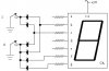
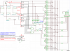
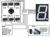
I´m trying to make something like (shift gear light) but diferent, and the difference is that i have a 7 segments that indicates the gear that i´m in the moment ex: (1,2,R,N.etc...). I´ve found in the web something like this but it only had one switch and i need a schematic that has at least 8 switchs for (1,2,3,4,5,N,R,P) first gear, second gear, third, fourth, fifth, Neutral, Rear and finally Parking.

I do not no programing and don´t have the tools to do it.

I´ve uploaded the same image here to that will help explain on what i really want.
https://img178.imageshack.us/my.php?image=7segmentshiftgearprojechl2.jpg

If anyone understand my explanation or need some details info or thinks it has a better way to do the same exact thing please tell me i would like to know.

Best regards to everyone and thanks in advance
 

Attachments

  • 7 segment shift gear project.JPG
    7 segment shift gear project.JPG
    86.4 KB · Views: 946
Last edited:
As you know this is s 7 segment display. It has segements A,B,C.D,E,F and G.
Which segments are lit up to display N and R ?
 
Answer to N and R 7 segment light

k7elp60 said:
As you know this is s 7 segment display. It has segements A,B,C.D,E,F and G.
Which segments are lit up to display N and R ?

Hi. Thanks for the interest in it. As you may know the 7 segments display can´t show many letters as a 16 segment.
alphanumeric-led-font.jpg

But since i can´t find any to buy(if you know any online store that sells them and ships them to Europe EVEN BETTER), i´ll use a 7 segment and for the N and R i was thinking in some kinda simbol like this..

This for the Neutral:
Neutral gear simbol for Shift gear light.JPG
This for the Reverse(If you notice its the way you have to move the gear knob to put the reverse):
Reverse gear simbol for Shift gear light.JPG

For anyone thinking that the only thing i did was the concept of the project..
I already made a circuit using OR, AND,XOR Gates i made it first on EWB(If anyone wants the file i can post it here). In the EWB it worked really well just as i wanted but then i made the circuit on a Breadboard and when i was about to test it i noticed that it worked as well but with something really weird.
As i remember for example a OR gate when one of the In´s is at 1 satge(in my circuit 5v) at the Out of the gate we should have 1 as well(5v) but when i put both the In´s at 0 stage (0v), in the Out i have 2v ALWAYS in every OR gate.

Result: all LED´s in the 7 segment are turned on but when i simulate a gear actuating the Switch (for example the first gear) it slightly increases the brightness.

It looks like this:
Picture 4.JPG

If i wasn´t clear enough just tell me i´ll be glade to clarify any question.
Best regards
 
Griever said:
This for the Neutral:
View attachment 16401
This for the Reverse(If you notice its the way you have to move the gear knob to put the reverse):
View attachment 16402

I used to have a Suzuki 380cc two stroke triple (1975 model?), it had a seven segment display between the speedo and rev counter, it displayed 1-6 for the gears, but I can't remember what it did for neutral?.
 
Nigel Goodwin said:
I used to have a Suzuki 380cc two stroke triple (1975 model?), it had a seven segment display between the speedo and rev counter, it displayed 1-6 for the gears, but I can't remember what it did for neutral?.

Do you have the schematic of it?

And other thing you don´t know why the Gates even when the out should be 0 (0v) it gives me 2v??
 
Griever said:
Do you have the schematic of it?

No, it was standard on the bike, but there can't have been much, it's a simple thing to do.

And other thing you don´t know why the Gates even when the out should be 0 (0v) it gives me 2v??

As already suggested, use a bunch of diodes to make a hardware wired ROM.
 
Griever said:
Hi. Thanks for the interest in it. As you may know the 7 segments display can´t show many letters as a 16 segment.
View attachment 16399

But since i can´t find any to buy(if you know any online store that sells them and ships them to Europe EVEN BETTER), i´ll use a 7 segment and for the N and R i was thinking in some kinda simbol like this..

This for the Neutral:
View attachment 16401
This for the Reverse(If you notice its the way you have to move the gear knob to put the reverse):
View attachment 16402

For anyone thinking that the only thing i did was the concept of the project..
I already made a circuit using OR, AND,XOR Gates i made it first on EWB(If anyone wants the file i can post it here). In the EWB it worked really well just as i wanted but then i made the circuit on a Breadboard and when i was about to test it i noticed that it worked as well but with something really weird.
As i remember for example a OR gate when one of the In´s is at 1 satge(in my circuit 5v) at the Out of the gate we should have 1 as well(5v) but when i put both the In´s at 0 stage (0v), in the Out i have 2v ALWAYS in every OR gate.

Result: all LED´s in the 7 segment are turned on but when i simulate a gear actuating the Switch (for example the first gear) it slightly increases the brightness.

It looks like this:
View attachment 16403

If i wasn´t clear enough just tell me i´ll be glade to clarify any question.
Best regards
If you only want the segments for each different condition lit and not the segments dim and the specific ones bright I can help you, but I need to know the type of display CA or CC and the recommended current per segment and the voltage per segment. As Common Anode or Common Cathode depends on the polarity of the DC voltage to drive them. Some displays have more than one LED in the segment. So I also need to know what voltage(DC volts) you are going to use to drive the displays with also. Knowing this I can draw you a typical circuit for the segements and you will be able to complete all the segment you wish to drive.
 
k7elp60 said:
If you only want the segments for each different condition lit and not the segments dim and the specific ones bright I can help you, but I need to know the type of display CA or CC and the recommended current per segment and the voltage per segment. As Common Anode or Common Cathode depends on the polarity of the DC voltage to drive them. Some displays have more than one LED in the segment. So I also need to know what voltage(DC volts) you are going to use to drive the displays with also. Knowing this I can draw you a typical circuit for the segements and you will be able to complete all the segment you wish to drive.

Very appreciated.

I´m using a 7 segments with CA. To drive it i´m using 5v with the 7805L regulator but if needed i also have LM1084IT-12 (12v regulator) the IC i made works fine but has that problem i mencioned. It uses 30 OR gates 5 XOR gates and 2 AND gates and finally 8 NO switchs.

If you can make a more simple circuit that does the same thing i´ll be very grateful.
 
Griever said:
Very appreciated.

I´m using a 7 segments with CA. To drive it i´m using 5v with the 7805L regulator but if needed i also have LM1084IT-12 (12v regulator) the IC i made works fine but has that problem i mencioned. It uses 30 OR gates 5 XOR gates and 2 AND gates and finally 8 NO switchs.

If you can make a more simple circuit that does the same thing i´ll be very grateful.

For each segment you want to light, you need a diode, such as a 1N4148 - and you repeat this for each number you want to display.

So for number '1' which only uses two segments, you require only two diodes, but for number '8' you would require 7 diodes.

So no IC's at all, just a bunch of diodes and seven resistors (one for each segment).

Your current solution is some what over engineered! :D
 
A lot of auto gearboxes have a selector switch already on the top of the gearbox for the autobox ecu to know which position is selected. I'd personally use that to get the signal to find out which gear is selected.
 
Nigel and I are thinking alike, mine show digits one and four.
 

Attachments

  • 7 SEGMENT DRIVE.JPG
    7 SEGMENT DRIVE.JPG
    19.7 KB · Views: 391
k7elp60 said:
Nigel and I are thinking alike, mine show digits one and four.

Nothing unusual in that, it's the way it's always been done - I'm sure my Suzuki was probably done like that?.

For those of you who remember PC cases with digital 'speed' displays on the front?, those were simply wired in that same way - merely showing the position of the 'Turbo' switch, not actually measuring anything.
 
:) Thank you everyone, you guys are awesome.
Nigel Goodwin and k7elp60 Thank you Thank you Thank you Thank you Thank you Thank you Thank you Thank you Thank you Thank you Thank you Thank you Thank you Thank you Thank you Thank you Thank you Thank you :) .
Very appreciate
 
Thank you...
But Cars is negative ground.
So this shema contacs (+) to pass.Maybe this is a problem.
And circuit is revise required.
(I think for revise).
 
For Negatif Chassis revise...

... Circuit Diagram ;
 

Attachments

  • 7 segment schematic help konulu sorusuna cevabım Negatif Şase.png
    7 segment schematic help konulu sorusuna cevabım Negatif Şase.png
    43.9 KB · Views: 328
Status
Not open for further replies.

New Articles From Microcontroller Tips

Back
Top