Electro Tech is an online community (with over 170,000 members) who enjoy talking about and building electronic circuits, projects and gadgets. To participate you need to register. Registration is free. Click here to register now.
Welcome to our site! Electro Tech is an online community (with over 170,000 members) who enjoy talking about and building electronic circuits, projects and gadgets. To participate you need to register. Registration is free. Click here to register now.
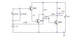
The input 500pF variable capacitor and 200µH inductor form a tuned circuit for the standard 535-1605 kHz AM frequency band in the US. The first stage is a darlington common-emitter amplifier biased by the 120k resistor. The output of the darlington stage is further amplified by the third transistor, also configured as a common-emitter amplifier. The circuit simply amplifies the AM RF signal and has no detector so the AM modulated information is not recovered.
The circuit is very simple and would have poor selectivity and performance.
This site uses cookies to help personalise content, tailor your experience and to keep you logged in if you register.
By continuing to use this site, you are consenting to our use of cookies.