micael
New Member
Hi,
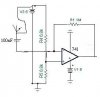
I m trying to amplify the voltage from a 433MHz flexi whip antenna which is connected on a strip board.
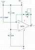
I have connected 5v supply to the antenna as shown in the schematic (..accident) ending with a circuit(on a stripboard) that works at 200MHz, 300MHz and sometimes 420MHz but not at 433MHz!!!!!
Any ideas whats going on with this circuit?
I m trying to amplify the voltage from a 433MHz flexi whip antenna which is connected on a strip board.
I have connected 5v supply to the antenna as shown in the schematic (..accident) ending with a circuit(on a stripboard) that works at 200MHz, 300MHz and sometimes 420MHz but not at 433MHz!!!!!
Any ideas whats going on with this circuit?
Attachments
Last edited:
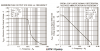
") . 400MHz is far too high for any op-amp, you need RF amplifiers or the best option, buying a ready made unit. Making anything for these frequencies on stripboard will not be sucessful, not at least without extreme care.
. 400MHz is far too high for any op-amp, you need RF amplifiers or the best option, buying a ready made unit. Making anything for these frequencies on stripboard will not be sucessful, not at least without extreme care.