Continue to Site

Welcome to our site!

Electro Tech is an online community (with over 170,000 members) who enjoy talking about and building electronic circuits, projects and gadgets. To participate you need to register. Registration is free. Click here to register now.

  • Welcome to our site! Electro Tech is an online community (with over 170,000 members) who enjoy talking about and building electronic circuits, projects and gadgets. To participate you need to register. Registration is free. Click here to register now.

Antenna conversion, Loop to Straight wire

Status
Not open for further replies.

heida11

New Member
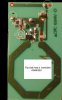
Attached is a picture of a surplus transmitter [433 Mhz].
No specs available.

The manufacture of other RF modules I use states that a straight wire
quarter wave antenna provides a measured improvement over the loop antenna.

The improvement was enought for me to pose this question --

How would I change this loop configuration to a straight wire
antenna.

I know I am not providing much info, but it's is all I have.

Thanks for any help.
 

Attachments

  • tv_007.jpg
    tv_007.jpg
    34.6 KB · Views: 282
Some general comments -

Ultimately what matters is the power that ends up at the receiver and that is the result of the power delivered to the transmitting antenna as well as the efficiency, radiative pattern and gain of the antenna.

A transmitter delivers power to a load - in this case the load is the antenna. Maximum power will come from the transmitter when the load (impedance) matches the requirements of the transmitter. When there is a mismatch, less power is output and protective circuitry in the transmitter is likely to reduce the power. Note that some transmitters are equipped with circuitry to assure a more constant match.

The loop antenna shown is likely to be matched to the transmitter. A wire is likely to behave differently, as a load, than the loop and unless you deal with the corrections, it is likely to result in a mismatch. If you deal with the mismatch you're still not done. Note that proximity of metal, flesh and other materials affects the behavior of an antenna.

Once power is delivered to the antenna it has to radiate. Ideally it radiates all of the power as RF, none as heat. Ideally it radiates the power in the desired direction and none in undesired directions. A loop will radiate power differently than a wire. You might deliver less power to the wire but if it radiates it more effectively so that the net to your receiver is greater then you've made an improvement.

There's a lot to consider here. Experimenting might be your best option but note that there is some risk that you might damage the output of the transmitter. You might calculate or measure the impedance of the loop at the frequency of interest then design a suitable matching section for a wire. It's possible that the loop is a common design and someone here already knows how it behaves (and will share that with us).

Best of luck.
 
stevez is right. The engineer of this transmitter probably designed the loop antenna to provide a good impedance match to the output transistor for best signal radiation and stability within the limits of the size of the pc board. Probably best to just leave it as is. :wink:
 
Status
Not open for further replies.

Latest threads

New Articles From Microcontroller Tips

Back
Top