Continue to Site

Welcome to our site!

Electro Tech is an online community (with over 170,000 members) who enjoy talking about and building electronic circuits, projects and gadgets. To participate you need to register. Registration is free. Click here to register now.

  • Welcome to our site! Electro Tech is an online community (with over 170,000 members) who enjoy talking about and building electronic circuits, projects and gadgets. To participate you need to register. Registration is free. Click here to register now.

astable help needed

Status
Not open for further replies.

uneducated

New Member
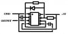
I need an astable 555 timing circuit with adjustable duty cycle (from 10% to 90%) and also with an adjustable frequency. So far I have figured a circuit which allows me to do this in a way, but I have to adjust the on time and off time separately.
Take a look at the attached image and you can see two resistors (pots). Adjusting one of these will allow a longer/shorter on time, and the other a longer/shorter off time.
Is there a way that I can use one adjustment to adjust the duty cycle, and another adjustment for the frequency, but without affecting one another. eg. turn the frequency up without adjusting the duty cycle?
 

Attachments

  • 555.JPG
    555.JPG
    8.6 KB · Views: 114
Over how wide a frequency range?
 
This is a harder probelm than it seems at first. Here is one idea. The duty cycle is adjusted by the center tapped resistor on the left side of the diagram, and the frequency by the variable resistor just over the left op-amp. The range can be changed by changing the timing capacitor. The op amp must have sufficient bandwidth for the frequency you want.

The simulation waveform demonstrates a couple different frequencies and duty cycles.
 

Attachments

  • VarFreq&Duty.JPG
    VarFreq&Duty.JPG
    178.4 KB · Views: 128
Looking at the diagram ... the pot over the left op amp is variable to adjust the frequency (gain)? But the center tapped resistor (supposing a trimpot) will adjust both the duty cycle and frequency ... what I am looking for is ...
1. adjust duty cycle between 10% and 90% depending on the needed supply
2. adjust the frequency between ~200Hz and ~3Hz
3. adjust duty cycle and frequency independently from each other (eg. one does not affect the other)
The diagram I have given (as I said before) will adjust the on and off times independently, thus I can adjust both to the specified requirements. Basically using a 1uF capacitor and 2 x 250k potentiometers, I can adjust the frequency between 720Hz and 2.88Hz, and can adjust the duty cycle between 0.398% and 99.602%. The problem is to adjust the frequency, I need to adjust both resistors in an equal manner.
What I am aiming for is to be able to drop the frequency down as low as it will go (~3Hz would be good), then adjust the duty cycle to get the required percentage of on versus off time, then turn the frequency up until operation speed is adequate. If I increase the frequency and the duty cycle changes as a result then it will not work ...
 
The diagram give you a circuit where frequency and duty cycle are adjusted independently. The center tapped resistor adjusts duty cycle, as I originally stated.
 
Just thought ... perhaps using an astable to reset another astable (or monostable) ... maybe this would be easier using a 556?
 
The duty cycle range exceeds your requirements. The picture doesn't show everything.
 
I don't see how your circuit would work considering there is nothing attached to the control voltage or discharge pins ... and where do I get the output from, considering this is being fed back through into the trigger?
 
Last edited:
Just thought ... perhaps using an astable to reset another astable (or monostable) ... maybe this would be easier using a 556?

The problem with that is, when the frequency is changes, the range for the duty cycle is no longer valid. The solution must use a method that automatically scales.
 
I don't see how your circuit would work considering there is nothing attached to the control voltage or discharge pins ... and where do I get the output from, considering this is being fed back through into the trigger?

Control and discharge isn't needed for this circuit. The output comes from the output pin, being used for feedback doesn't change anything.
 
BTW, my solution is just one idea. I would be interested in seeing other ideas as well.
 
Status
Not open for further replies.

Latest threads

New Articles From Microcontroller Tips

Back
Top