Continue to Site

Welcome to our site!

Electro Tech is an online community (with over 170,000 members) who enjoy talking about and building electronic circuits, projects and gadgets. To participate you need to register. Registration is free. Click here to register now.

  • Welcome to our site! Electro Tech is an online community (with over 170,000 members) who enjoy talking about and building electronic circuits, projects and gadgets. To participate you need to register. Registration is free. Click here to register now.

astable mutivibrator to a display

Status
Not open for further replies.

Christy

New Member
Hi there,
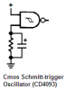
I'm doing a project and in my project it has a Schmitt trigger configured as an astable multivibrator(CD4093) to generate a clock which is connected to a clock pin of timer CD4020...the astable multivibrator can have preset value to gennerate a clock of the timer CD4020 which can be calculated.My question is how can i display the status of the astable multivibrator,so i know how much time is left for generating a clock(say 30 minutes) for the timing IC CD4020?
 
hi Christy,
You could use LED's on the outputs of the CD4020 to indicate high or low of the pin.
This would give a Binary display of the 4020 output pin states.

Or are you asking for an LCD type display.??
 
thanks for your response to my question...any form of display can do,u say i should connect led's to the output pins of cd4020 but the output pins are driving transistors to activate a buzzer...how can i achieve this?is there a better way?
I'm new to designing a project.
 
thanks for your response to my question...any form of display can do,u say i should connect led's to the output pins of cd4020 but the output pins are driving transistors to activate a buzzer...how can i achieve this?is there a better way?
I'm new to designing a project.

hi,
For a CD CMOS device I would use an intermediate transistor to drive the LED's.
If you post your circuit, we can show how to add these resistor/transistor/led drivers.
 
there is the circuit i wish to have the status of the astable multivibrator
 

Attachments

  • anti-sleepalarmCI-01_Mar2010.pdf
    216.6 KB · Views: 381
Maybe I am missing something and this is not quite on topic as to the question but looking at the circuit when the reset button S1 is pressed it places a dead short across C1 the 1,000 uF filter cap and also places a dead short to ground from your 12 volt supply to ground through diode D1 which will become very unhappy real quick. Am I seeing that correctly?

Additionally looking at the P and N terminals which I assume to be 230 VAC that powers a lamp and fan. With RL1 contacts in the N/C state there is a dead short across line voltage as I see it. Won't this cause bad things to happen?

Unless I am missing something in this, the least of the worries of anyone building this circuit up is what the multivibrator is doing.

Ron
 
yesyes, yes basically i want to know how much time is left in the cycle.and Relaodron i get what you saying,but I'm a beginner is project design,this circuit has been tested, which has a stamp which states it has.
 
The CD4020 is a binary counter (not really a timer). In this circuit it seems to trigger certain things when the counter has reached certain numbers. The simplest way to display the *steps* of the counter would be a row of LEDs that show the state of each output on the CD4020 and therefore showing the current counter value in a binary way. You could convert that to, say, 7 segment by using a binary to 7-segment converter IC.

However, to show this as *time* and not counter steps would be considerably more difficult. There is currently no way to tell/measure the period of the astable multivibrator in a digital way. One way to approach this would be to measure the duration of one period and multiply that by the number of counter steps or so.
Another way would be to use a different kind of clock generator that provides some sort of info on its period. Though I don't know if that even exists...
 
The multivibrater oscillator is a joke. The capacitor C2 has its polarity backwards.
I have never seen any circuit work properly from that site in India.

A single Schmitt-trigger inverter or a Schmitt-trigger gate connected as an inverter makes an oscillator and its capacitor always has the correct polarity.

Schmitt-trigger gates should never have their inputs tied together. The unused input should be disabled so that only one input is active in the circuit.
 

Attachments

  • Cmos Schmitt-trigger oscillator.PNG
    Cmos Schmitt-trigger oscillator.PNG
    3.7 KB · Views: 354
Thanks for the tip off Audioguru,i should modify this circuit.and Yesyes,i prefer to convert the binary to a seven segment,how should i go abot doing that?
 
There are ICs that convert from binary to 7-segment. Usually they are single digit, so 4 bit. The counter in that circuit has 14 bit, so you would need 4 of these converters. Then just connect the 4 inputs of teh converter to the outputs of the counter.
You may want to look for a converter that can handle hexadecimal (0-9 and A-F), not just decimal numbers 0-9. Then just connect 7 segment LED displays to the converters. You might need some extra drivers depending on the displays you want to use.

But again, this will show the counter value of the CD4020, not some time.
 
yesyes, yes basically i want to know how much time is left in the cycle.and Relaodron i get what you saying,but I'm a beginner is project design,this circuit has been tested, which has a stamp which states it has.

If you choose to build this I suggest yopu look at just a few of the bad problems. Do not even think about applying mains power as it shows. The reset is completely wrong also. That seal means nothing as there is absolutely no way the circuit would work as drawn. The circuit is garbage. Also, I suggest you already have the CD4020 as I believe it is obsolete? You may want to check on that or possibly sub a CD4060 and redesign everything wrong with the circuit.

Good Luck
Ron
 

Attachments

  • CD4020 Bad Ckt.gif
    CD4020 Bad Ckt.gif
    53.3 KB · Views: 1,378
thanks yesyes for your help.I understand it's a binary counter and not a timer.Is there any sites that you recommend that could help assist me with this?
 
Thanks reloadron,i will find help to redesign the whole circuit.will build it on an electrical software before i really build it taking your precautions to mind.
 
Christy, let me share with you part of the problem you will face trying to read the output(s) of the CD4020.

The way the circuit is supposed to work is that clock pulses enter the 4020 on pin 10 the clock in. The counter is advanced one count on the negative transition of each incoming clock pulse. The counter is reset to the zero state by a logical “1” at the reset input pin 11independent of clock. (Note in the drawing the counter reset is tied to logic high so won't count but anyway moving along). All the counter knows is that it counting pulses it has no clue what they mean, it has no regard to time. Hold that thought.

In this case they try for a clock of .21 seconds and if we do the math for the clock circuit (which as AudioGuru points out is a lousy clock) it would be .207 second but I guess we can say .21 second as it is close enough for this. So lets move along to actual time in hours. We know there are 60 seconds to a minute and 30 min = 1/2 hour. Therefore 1/2 hour of time = 1,800 seconds. Since our clock pulses are .21 seconds it will take 1,800 / .21 = 8,571.43 pulses for 30 min. Forget the .43 but we still have 8,571 pulses to make our 30 min. If you wanted to display this numerically on a display first it would not be easy and second the numbers seen would not mean much.

Now if you look at T1, T2, and T3 in the circuit. For the buzzer to beep they all must be on and in saturation acting as a switch. (Note: I see 22 KΩ base resistors, I believe that is also wrong, I believe 2.2KΩ would be about right). All three of those transistors, to be turned on need the logic out on Q1, Q5 and Q14 to be logic high. Now you figure out the bit count. Think powers of two and bit weight. All the buzzer will do is a beep when all of those bits are logic high. As soon as any one of them goes low in the count the beep stops. Eventually Q8 and Q14 will hit a high on both bits. When N3 pins 8 & 9 are high pin 10 is low. That low is applied to pins 12 & 13 of N4 making its output pin 11 high and turning on T4 which should in turn allow RL1 to energize. We already covered the disaster at the normally closed contacts of RL1 and mains voltage.

Now if you want to get started with timer and counter circuits I would suggest you start with more simple circuits using binary counter dividers and gain an understanding of simple binary outputs. Chips like the 74192 nd 74193 come to mind or their CMOS brothers. Start simple with 1, 2, 4, 8 and then move along.

You can ask your question(s) in other forums but I believe you will get the same answers.

Ron
 
Hi Ron,

I really do understand what you saying.Thanks for your help though.I do trust your answers ,no need to ask other forums.Thanks again,will give this a try.If i do struggle,I will be back for some little help.
 
Hey Everybody,
Can someone help me on what driver IC to a seven segment display i could use in this circuit of mine?
 
Hey Everybody,
Can someone help me on what driver IC to a seven segment display i could use in this circuit of mine?

hi Christy,
A 7 segment driver would not be helpful on your existing display, a simple resistor/transistor/LED on each pin would give you a Binary display.
Like Ron, I would suggest a new design.

OT.
Give my regards to PE, my second home.
Located along the old Cape Rd, towards Little Chelsea..:)
 
haha.oh wow,will do.I'm studying at UPE(now called Nelson Mandela Metropolitan University).I'm actually from Johannesburg,just in PE to study,less distractions at PE than in Johannesburg...By the way,could you help me with that simple resistor/transisto/LED design,could you do a schematic of it,please,just a rough idea.
Thanks eric
 
Status
Not open for further replies.

New Articles From Microcontroller Tips

Back
Top