SentinelAeon
Member
I have a problem with my audio setup where the audio input line signal is to strong to the point where it distorts audio.
My audio setup looks like this:
Pc -> usb dac -> amp
So far the only solution is to lower the pc volume down to 50% (and this solution isnt OK for me, i need my volume in windows at 100% !). The signal is still way to strong and i would like it lower, but at least the distortion is gone. All components were tested elsewhere and it came down to amp being the culprit.
So since lowering the pc volume to 50% solved the issue, i thought it should be easy enough to just put a resistor on each channel between dac and amp. I had to use a 50k resistor to actualy remove distortion. But for some reason this completely ruined the sound quality, it became muddy, like someone cut certain frequencies. I fail to understand why because lowering the pc volume should be basicaly the same as if i put a resistor on the L and R line and lower the volume like that, right ?
As for the reason why that is so, someone on this forum i belive, said that probably the amplifier is designed with mobile phones in mind and the signal i get from DAC is a lot stronger than what my mobile phone can supply. Meaning it overpowers the amp and distorts.
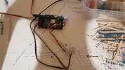
On the attached image you can see the amp and how it's connected. I soldered the input wires directly to 3.5mm female input jack on the amp for the sole reason to not have a 3.5mm male jack sticking out near volume pot. Just to make sure there is no misunderstanding.
My audio setup looks like this:
Pc -> usb dac -> amp
So far the only solution is to lower the pc volume down to 50% (and this solution isnt OK for me, i need my volume in windows at 100% !). The signal is still way to strong and i would like it lower, but at least the distortion is gone. All components were tested elsewhere and it came down to amp being the culprit.
So since lowering the pc volume to 50% solved the issue, i thought it should be easy enough to just put a resistor on each channel between dac and amp. I had to use a 50k resistor to actualy remove distortion. But for some reason this completely ruined the sound quality, it became muddy, like someone cut certain frequencies. I fail to understand why because lowering the pc volume should be basicaly the same as if i put a resistor on the L and R line and lower the volume like that, right ?
As for the reason why that is so, someone on this forum i belive, said that probably the amplifier is designed with mobile phones in mind and the signal i get from DAC is a lot stronger than what my mobile phone can supply. Meaning it overpowers the amp and distorts.
On the attached image you can see the amp and how it's connected. I soldered the input wires directly to 3.5mm female input jack on the amp for the sole reason to not have a 3.5mm male jack sticking out near volume pot. Just to make sure there is no misunderstanding.
Attachments
Last edited:
")