Continue to Site

Welcome to our site!

Electro Tech is an online community (with over 170,000 members) who enjoy talking about and building electronic circuits, projects and gadgets. To participate you need to register. Registration is free. Click here to register now.

  • Welcome to our site! Electro Tech is an online community (with over 170,000 members) who enjoy talking about and building electronic circuits, projects and gadgets. To participate you need to register. Registration is free. Click here to register now.

Audio Level Meter to control seperately powered lights

Status
Not open for further replies.

ovfkho0j

New Member
Ok, first of all I'm a total beginner (but with a good sense for things), so please bear with me.

I'm interested in building a simple Audio Level Meter. I've found several scematics and the proper IC (i think so at least). However, all of these are to control LEDs that are attached to the circuit board itself. What I want to do is to use the circuit to control seperate lights that have their own power which is not coming from the circuit.

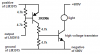
here is an example IC that i found which I think it close to what I want:
**broken link removed**

however, I don't really know what I would need to do differently. Basically I want the lights to function just like the LEDs would, to turn on when the audio level passes a certain level. However the LEDs draw their power directly from the circuit board, where as I just want the audio signal to turn the appropriate lights on and off which are powered seperately.

Any help would be greatly appreciated. Please let me know if I left anything out.
 
they are 4" cold cathode tubes, they are powered from an inverter which is powered via molex. here's the info i could find:

Input voltage of inverter: 12v
Output voltage of inverter: 680v
Current draw: 5.0mAv
 
So you need a bunch of high voltage switches that are driven from the LM3915. Small relays would switch slowly and are not rated for such a high voltage.
 
sorry if it's a pain in the butt, but could you give me an example of such switches? and how would i connect it? would they interrupt the -negative line to the lights?
 
Since the lights have a negative line then DC must be used so a transistor can switch them. A transistor cannot switch AC.
Each light needs a circuit like this from each output of the LM3915:
 

Attachments

  • Audio Level Meter.PNG
    Audio Level Meter.PNG
    8 KB · Views: 148
well honestly i'm not really sure about the lights themselves. they connect with a two-pin connecter like in this picture:
**broken link removed**
those are the male pins going out from the inverter which the lights would plug into.

so i just assumed that since there's two pins one is + and one is - (it's gotta have a + and -, right? please excuse my retardation).

so all i wanna do is trigger those lights instead of LEDs. but i realize the LEDs are being powered by the circuit board, while the cold cathodes already come with inverters, so it would be a pain in the butt to try to integrate it all onto one circuit board... or would it?
 
mike12da said:
well honestly i'm not really sure about the lights themselves.
so i just assumed that since there's two pins one is + and one is - (it's gotta have a + and -, right?
No. AC doesn't have a + wire and a - wire.
I looked in Google and many companies sell cold cathode lights with cheap inverters but couldn't find out if the inverter produces AC or DC. A transistor won't work with AC.

so all i wanna do is trigger those lights instead of LEDs. but i realize the LEDs are being powered by the circuit board, while the cold cathodes already come with inverters, so it would be a pain in the butt to try to integrate it all onto one circuit board... or would it?
No. An LED also has only two wires to connect. The power can come from a separate power supply if you want. The LM3915 is designed to directly drive LEDs.
I made this sound level bar-graph with an LM3915 and some LEDs. It has a microphone and a rechargable battery.
 

Attachments

  • Sound Level Indicator 003.jpg
    Sound Level Indicator 003.jpg
    31.5 KB · Views: 146
ok, so i'm apparently way off.

i looked it up though and it looks like the inverters are DC (usually 12V)
here's an image on the inside of one:
**broken link removed**
not sure what you can gather from that.

so what kind of IC would I need for this kindof thing? I was just looking for audio level meters and they're usually LEDs, but i just wanted to use the same idea and power these CCFLs instead. i know i've got a lot to learn before i can actually do this, but i wanted to see how reasonable it would be to do in the first place. seems like it's not toooooo complicated.
 
mike12da said:
ok, so i'm apparently way off.
Yes.

i looked it up though and it looks like the inverters are DC (usually 12V)
An inverter uses a power supply of 12VDC and makes an output of 680V probably AC.

so what kind of IC would I need for this kindof thing?
If the inverter's high voltage output is AC then it might be able to be switched with a high voltage triac instead of a transistor.
 
Status
Not open for further replies.

Latest threads

New Articles From Microcontroller Tips

Back
Top