Continue to Site

Welcome to our site!

Electro Tech is an online community (with over 170,000 members) who enjoy talking about and building electronic circuits, projects and gadgets. To participate you need to register. Registration is free. Click here to register now.

  • Welcome to our site! Electro Tech is an online community (with over 170,000 members) who enjoy talking about and building electronic circuits, projects and gadgets. To participate you need to register. Registration is free. Click here to register now.

Auto Controller needed

Status
Not open for further replies.

iONic

Member
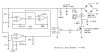
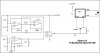
The attached schematic shows a "buck puck' LED driver with control and reference pins. Essentially changing the resistance value change the % of the available 700mA current applied to the attached LED's(Luxeon III's in my case).

Instead of manually changing the brightness I want a chip to do the work.
For Example: Beginning at 40% initially and each step (aprox 1 min.) increasing 5% until 100% is reaches. Once 100% is reached it should stay at 100%.

Any suggestions on what type of chip I would need to accomplish this?
My friend has a "MicroChip" Programmer board so it would be good to use something I can program.

Essentially I want the LED's to begin at 40% brightness and work their way up to 100% within about
15 minutes.
 

Attachments

  • BuckPuckReg.gif
    BuckPuckReg.gif
    39.7 KB · Views: 175
Nothing! 20 people have reviewed the post and nobody has any suggestions!

Was hoping for a starting point, at least.
 
The module you have uses a pot for dimming.
A different circuit uses pulse-width-modulation for dimming. Then a microcontroller can control the dimming.
 
I don't know if your module can be dimmed with pulse-width-modulation.
 
Not sure if this means it can or not!

External Pulse/Strobe Control

Figures 13 and 14 show two methods for low speed pulsing or high speed flashing operation. In Figure 13, a TTL/CMOS logic signal is applied to the control(Ctrl) input of the 3021. The output current will be zero when the control signal is high. Note that the input needs to source a minimum of 4.75VDC into a 1Kohm input impedance. Also, as is also the case with a dc control signal, the logic input ground to be common to the LED-output terminal.

Figure 14 shows an inverted input configuration using a 2N4403 or other PNP switching transistor. In this case, a logic high will cause the output to be "on". In either configuration, the rise and fall times of the output will be 25micro sec or less. A pulse frequency up to 10kHz may be used.
 

Attachments

  • PWM.gif
    PWM.gif
    32.2 KB · Views: 132
Last edited:
10kHz is fine. You can't see it blink when the frequency is higher than about 50Hz unless it is moving or you are moving your head.
 
Then, assuming 10KHz is 100%, It would be possible to get the desired effect from a freq range of 40KHz - 100KHz. Yes?
 
You vary the duty cycle with pulse-width-modulation, not with the frequency.
 
I have since found a circuit that appears to be able to do what I was looking for without the need for programing a chip, which I am at this time unable to do.

The circuit was designed by Bill Bowden.. and the description is as follows:

In this circuit, a 120VAC lamp is slowly illuminated over a approximate 20 minute period. The bridge rectifier supplies 120 DC to the MOSFET and 60 watt lamp. A 6.2K, 5 watt resistor and zener diode is used to drop the voltage to 12 volts DC for the circuit power. The bridge rectifier should be rated at 200 volts and 5 amps or more. In operation, a 700 Hz triangle waveform is generated at pin 1 of the LM324 and a slow rising voltage is obtained at pin 8. These two signals are compared at pins 12 and 13 to produce a varying duty cycle rectangular waveform at pin 14, which controls the MOSFET and brightness of the 60 watt lamp. When power is applied, the lamp will start to illuminate within a minute or so, and will slowly brighten to full intensity in about 20 minutes. You can make that longer or shorter with adjustments to the 270K resistor at pin 9. The 2.2 ohm resistor and .015uF cap connected to the lamp serve to suppress RFI. The diode at pin 9 and 10K resistor on pin 8 are used to discharge the 3300uF cap when power is removed. Power should be off for a few minutes before re-starting.

I have altered it but am not sure if this will work or not. Please let me know what you think. I'm not sure if I need more than 5V for the LM324 section, but I do know I need the 5V Square wave out of pin 14.
 

Attachments

  • Original Circuit Sunrise Lamp.jpg
    Original Circuit Sunrise Lamp.jpg
    33.4 KB · Views: 135
  • Original Circuit Sunrise Lamp-modified.jpg
    Original Circuit Sunrise Lamp-modified.jpg
    34.9 KB · Views: 140
Last edited:
The old LM324 has an output high voltage that is 1.2V less than its power supply voltage when its load current is very low.
So if its supply voltage is 5.0V then its output high voltage is only 3.8V.
 
audioguru said:
The old LM324 has an output high voltage that is 1.2V less than its power supply voltage when its load current is very low.
So if its supply voltage is 5.0V then its output high voltage is only 3.8V.

Thus I will need a supply voltage of 6.2V. Not a Problem. Other than that do you think it should work? Given the reduced supply voltage,
12V - 6.2V, will the Cap need to be different to keep the 20 min ramp? Do you think there is a better Quad OpAmp for this?
 
Last edited:
Few opamps work with a supply as low as 6.2V.
Few opamps work with an input as low as 2.0V.

The LM358 dual and LM324 quad opamps along with the better MC3317x and MC3407x opamps work with a supply voltage down to 3.0V and their inputs work fine as low as ground.
 
Bottom line though, it's not the input voltage I will have a problem with, but the
5V output on pin 14.

I may actually have a few of those old LM324's and even the LM358's.
 
Status
Not open for further replies.

Latest threads

New Articles From Microcontroller Tips

Back
Top