Continue to Site

Welcome to our site!

Electro Tech is an online community (with over 170,000 members) who enjoy talking about and building electronic circuits, projects and gadgets. To participate you need to register. Registration is free. Click here to register now.

  • Welcome to our site! Electro Tech is an online community (with over 170,000 members) who enjoy talking about and building electronic circuits, projects and gadgets. To participate you need to register. Registration is free. Click here to register now.

Beck-EMF sensing circuit

Status
Not open for further replies.

Rusttree

Member
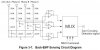
I'm trying to improve my BEMF-sensing circuit for a 3-phase BLDC motor. I found a circuit diagram in Freescale AN1914 that I would like to understand better. See a copy of the figure attached.

I understand the need for a voltage divider, but why the huge resistance values stacked up like that? It seems like 1.7Mohm of resistance form source to ground is a little excessive.
 

Attachments

  • freescale.jpeg
    freescale.jpeg
    29.9 KB · Views: 188
Hi,

Without looking at this in too much detail (yet), it could be that the line voltages were very high for that application. In that case sometimes multiple resistors are connected in series instead of using one resistor because the max voltage rating for the resistor would be exceeded if only one was used connected directly to the line. It's not a matter of power dissipation although that can also play a part in the choice of resistor values.
 
I agree with MrAl. What's more puzzling is the use of all those 27k resistors. Why 2 x 27k instead of 1 x 56k ?
 
I agree with MrAl. What's more puzzling is the use of all those 27k resistors. Why 2 x 27k instead of 1 x 56k ?

I suspect that the 2*27K, means two 27K's in parallel.?

I agree the notation is a little ambivalent.:rolleyes:
 
I guess the 27K resistors are series resistors.

The inverting inputs of all three OpAmps are connected to one 27K resistor of the DC_Bus.

Supposedly the non-inverting inputs for Phase A, B and C should ideally have double the voltage of the inverting input.

To make sure the resistors match in value (a 54K resistor is no standard value) two series resistors of 27K each are used.

I also guess the application has been published for three phase AC motors being driven at high voltage (440VAC between phases). A voltage of 100V across each resistor is a wise decision as metal film resistors are limited to 200V each.

Boncuk
 
Last edited:
Supposedly the non-inverting inputs for Phase A, B and C should ideally have double the voltage of the inverting input.
That makes sense; so that voltages equally above and below a reference value are sensed.
 
Status
Not open for further replies.

Latest threads

New Articles From Microcontroller Tips

Back
Top