Continue to Site

Welcome to our site!

Electro Tech is an online community (with over 170,000 members) who enjoy talking about and building electronic circuits, projects and gadgets. To participate you need to register. Registration is free. Click here to register now.

  • Welcome to our site! Electro Tech is an online community (with over 170,000 members) who enjoy talking about and building electronic circuits, projects and gadgets. To participate you need to register. Registration is free. Click here to register now.

Binary Clock help (sorry for numerous Clock threads)

Status
Not open for further replies.

Krumlink

New Member
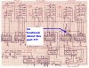
I diddnt want to hijack the Binary clock thread Robotbuilder started, so I started my own. On this schematic, He has SPDT switches to adjust time. What kind of switches should these be? I ordered toggle switches, but I am unsure now.:confused:

Link for original Thread with Binary clock:
https://www.electro-tech-online.com/threads/binary-clock.98/?highlight=binary+clock

Link for Schematic:
https://www.electro-tech-online.com/attachments/binclock-jpg.3546/

Link for Time adjust Switches:
https://www.electro-tech-online.com/attachments/adjust-jpg.3549/

Sorry for all the links, but makes it easier in the long run.

Thanks!

:D
 
The original thread mentions that they are momentary SPDT switches.

That means they are similar to pushbuttons in that they are spring loaded and only operate while you press the switch.

The toggle switches you ordered will stay switched until you toggle it back.
That could make it more fiddly but not impossible to adjust the time.

You could use cheap microswitches if you are not bothered about panel mounting them.

Edit: I just looked at the photo of the original clock and it does look like microswitches were used.
 
Last edited:
Good, Because I fixed the order for microswitches. How can I pull more mA out of the TTL outputs? I know about hooking them up to transistors, but That would take too many. Any advise that is simple? I am using cheapo red LEDs.
 
Hmmmm

Thanks for the suggestion, but Do you think that the TTL outputs will be able to drive the LEDs by themself?
 
Parts for clock arrive tomorrow. Cant wait! Promise to post pictures!
 
Started to prototype circuit on breadboard. I also put the switches inside the enclosure.

The LS series outputs about 8ma, i am uncertian if that will work. Going to prototyper circuit and hope for thebest.

Also, on the schematic it lists MSB then an arrow and LSB. What does this stand for?
 
Last edited:
I have the 1hz clock working. It works perfect. The 8ma is perfect for the LED. It is still pretty bright and easy to tell its on. Im happy :) Im going to finish it tonight!
 
Lol I did not finish it that night, I fell asleep on accident :(

But the question I have now is this:
The circled part of the schematic is confusing. It has x's and other marks that are confusing to me. Perhaps you could take a look and figure out what is going on?

Also, Ignore the circled blue part. I circled the wrong part rofl :eek:

AND! The LS series has a output of 16ma.
 

Attachments

  • binclockFIX.JPG
    binclockFIX.JPG
    241.6 KB · Views: 232
The x's are where the writer wants the lines erased. (But he was using ink.)

If you scrub out the x's and their lines you should have a readable schematic.
 
Ok thanks alot, I would hate to proceed and mess up the whole thing now if it fails its all your fault :D Im joking
 
Status
Not open for further replies.

Latest threads

New Articles From Microcontroller Tips

Back
Top