Continue to Site

Welcome to our site!

Electro Tech is an online community (with over 170,000 members) who enjoy talking about and building electronic circuits, projects and gadgets. To participate you need to register. Registration is free. Click here to register now.

  • Welcome to our site! Electro Tech is an online community (with over 170,000 members) who enjoy talking about and building electronic circuits, projects and gadgets. To participate you need to register. Registration is free. Click here to register now.

BJT Amps

Status
Not open for further replies.

jack23

New Member
Hello all,

I have a HW problem ( see attached PDF).

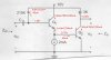
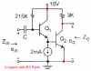
What I am confused about is the 2mA current source. What I am thinking is that the emitter current = the collector current = 2mA for Q1 ( the first transistor in the pair ). If this is the case, does that mean that the base current of Q2 is 2mA?

Also, since there is no voltage drop anywhere ( by way of resistors ) in the first transistor, how could there be a VCE1?

Any help would be greatly appreciated.
 

Attachments

  • scan0001.pdf
    278.1 KB · Views: 220
Last edited:
No, for Q1 the emitter current is the sum of the collector current and the base current. The emitter current will also equal the 2mA constant current, PLUS the base current of Q2.
 
Ok, so if I need to find the base current of Q1, then I would take the beta given, which is equal to 50, and say that Ic / 50 = Ib which would give

2mA/50 = 40uA??

So I would I go about calculating for base current of Q2?

Given your input Nigel, you said that Ie = 2mA + Ib( of Q2)

So then, Ib(of Q2) = Ie - 2mA

so that means that Ib of Q2 is the same as Ib of Q1, is that right???
 
jack23 said:
Ok, so if I need to find the base current of Q1, then I would take the beta given, which is equal to 50, and say that Ic / 50 = Ib which would give

2mA/50 = 40uA??

So I would I go about calculating for base current of Q2?

Given your input Nigel, you said that Ie = 2mA + Ib( of Q2)

So then, Ib(of Q2) = Ie - 2mA

so that means that Ib of Q2 is the same as Ib of Q1, is that right???

No, the Ie of Q1 will be more than 2mA, because it has to supply the base current of Q2 as well.

Personally I would say this is a really crappy (useless) partial circuit, and a really crappy question - I suspect the expected answers may require you to make a number of completely incorrect assumptions?.
 
To understand this improbable situation, I would write an equation for everything that you do know, and solve. Check for reasonableness (don't accept negative currents unless you understand them).

One worthwhile assumption is that the schematic is in error and 251K and 3K are also connected to 10V. Given the ridiculous circuit which would remain, it is probably true. It may be worth noting in your answer (you should request extra credit).

Ib1 is probably equal to Ic1/50, and is probably equal to (10-Vb1)/215K, and Ib2 is probably equal to Ie1 - 2mA. etc.
 
I don't think any assumptions are necessary to find the operating point. What's wrong with this analysis?
EDIT: This is what mneary said.:eek:
 

Attachments

  • bjt amp operating point.JPG
    bjt amp operating point.JPG
    36.4 KB · Views: 168
Last edited:
Roff, Thank you for your response. It is much clearer now.

I have two questions remaining:

1) I am assuming that, since there is no resistor resistors ( collector, emitter)
for the first transistor ( Q1), then the full 10V is dropped across Vce ( Vce = 10V) is this a reasonable assumption?

2) How were you able to add your own tex my PDF file? I would really like to know, that would really come in handy...

Thanks
 
I pressed my keyboard's Prt Scrn button then pasted your schematic into MS Paint.
I removed the grey background, cropped it then added the connection dots and text.
 

Attachments

  • PDF schematic.PNG
    PDF schematic.PNG
    17.6 KB · Views: 163
jack23 said:
Roff, Thank you for your response. It is much clearer now.

I have two questions remaining:

1) I am assuming that, since there is no resistor resistors ( collector, emitter)
for the first transistor ( Q1), then the full 10V is dropped across Vce ( Vce = 10V) is this a reasonable assumption?
No. Keep in mind that Vbe(2) is 0.7V, so Vce(1)=9.3V.

2) How were you able to add your own tex my PDF file? I would really like to know, that would really come in handy...

Thanks
When I opened your PDF, my cursor was crosshairs (apparently an Acrobat reader feature). I simply dragged the crosshairs across your schematic, then copied and pasted it into MS Paint, where I added the annotation.
 
Status
Not open for further replies.

Latest threads

New Articles From Microcontroller Tips

Back
Top