daveclifford95
New Member
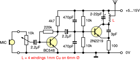
Hi, I am planning to build a FM transmitter for my school project. There are a lot of designs available on the internet and I simply don't know which to choose. I decided to choose a simple one from the cryptomuseum webpage. Its circuit is shown below.

I am new to RF design. Please forgive my ignorance. I would like to ask a couple of questions.
1) Why the antenna is wired to the inductor in the manner shown above? Won't the frequency of the signal be affected?
2) Why a potentiometer is connected to the mic instead of a fixed one? Is it because of the issue of impedance matching?
3) Could this circuit be improved somehow? Is there an alternative circuit instead of the one shown above?
4) I tried to analyze the feedback loop of the oscillator circuit (the LC tank with the second transistor) by hand but my equations got complicated quickly. The question is: Is the resonant frequency of the oscillator set solely by the LC tank or will it be affected by the 3pF capacitor in the positive feedback loop?
Thanks in advance for your patience and guidance.


