strokedmaro
New Member
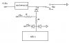
Please take a look at the attachment Ive drawn up and tell me if its possible. I could use voltage regulators but this would be easier. I also know there would need to be more inputs to the segment driver....just want to know if this would be safe or even possible. THANKS!!!
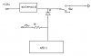
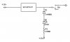
") Normal operation: solenoid has 12vdc on it constantly and is controlled by a switched ground supplied by a computer. I basically want to tap into that circuit using a lesser voltage (compatible with the hardware I currently have) to display a digit based on the combination of several solenoids. I know the 4511 is able to operate up to 18vdc but the logic used to make the correct inputs to the 4511 (again, what I have here and by the way not shown in the drawing) is 5.5vdc max. Any help appreciated!
Normal operation: solenoid has 12vdc on it constantly and is controlled by a switched ground supplied by a computer. I basically want to tap into that circuit using a lesser voltage (compatible with the hardware I currently have) to display a digit based on the combination of several solenoids. I know the 4511 is able to operate up to 18vdc but the logic used to make the correct inputs to the 4511 (again, what I have here and by the way not shown in the drawing) is 5.5vdc max. Any help appreciated!