Electro Tech is an online community (with over 170,000 members) who enjoy talking about and building electronic circuits, projects and gadgets. To participate you need to register. Registration is free. Click here to register now.
Welcome to our site! Electro Tech is an online community (with over 170,000 members) who enjoy talking about and building electronic circuits, projects and gadgets. To participate you need to register. Registration is free. Click here to register now.
I would like to say thank you very much to be able to answer my question.
Here what exactly what I want and what information that I already Have.
My main objective is to build an Amplifier for a microphone(Converting from PC headset to Aviation Headset).
What I have is :
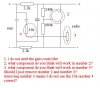
Attachment 1 : A circuit for Aviation Headset convert to PC headset(which is reversed with what I want)
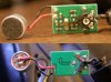
Attachment 2 : A circuit for the real Amplifier for Electret if connected to aviation input(which is a real circuit of aviation headset - which I want to built)
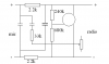
Attachment 3 : A circuit drawn by a person from another forum about decoding attachment 2 photo(but there is still unknown component. Which I really appreciate his help for drawing this.) He said that he did the best that he could do.
Some comparation between 2 items based on my information :
Aviation Microphone Sample 1 Specification :
Element Type: Noise-canceling electret
Frequency Response: 150Hz to 5 kHz
Operating Voltage (supplied by aircraft): 8-32 Volts DC
Matching Impedance: 150-1000 ohms
Sensitivity: -33±4 dB
(Ref: 0dB SPL=20.0uPa at 1 kHz with 10 Vdc 150 ohms AC load)
Aviation Microphone Sample 2 Specification :
DC Bias Supply: 8 to 16 volts, not polarity sensitive
Source Resistance: 220 to 2200 ohms
Output Voltage: 370 mV @ 114 dB spl re .0002 microbar
Noise Level: 120 dB spl re .002 microbar
PC Microphone :
Frequency response: 100 Hz – 10 KHz
Sensitivity: -42 dBV/Pa re: 0 dB = 1 Pa, 1 KHz
Test conditions: 3.0 V, 2.2 K ohm
Some Explaination :
There are 3 basic types of microphone used in aviation: Carbon, Dynamic and Electret.
Electret Microphones
A more recent development is the electret microphone. In an electret microphone the voice diaphragm is connected to two plates which sandwich a small piece of piezo crystal. As the pressure on the crystal varies, it produces a very small audio voltage which is picked up by the plates. This voltage requires considerable amplification to become useable and a small amplifier is directly connected to the piezo crystal. The amplifier requires a DC voltage to operate and in an aviation transceiver this is usually provided by the DC energising voltage present at the microphone input. The electret microphone, because of its small size and excellent frequency response, has become the commercial microphone of choice. However, in most electret applications, the output voltage level is designed to be much lower than that needed to fully drive aviation transceivers. In aviation applications, the electret mic is designed to have considerably more amplification to provide the 0.5 to 1.0 volts needed to drive an aviation transceiver.
Bottom Line:
Based on the data, what we need is the Voltage conversion and Impedance conversion, I need to study this for my experiment. I only have a basic electronic knowledge.
One more time I would like to thank you.. and looking forward to solve this problem.
I would like to say thank you very much to be able to answer my question.
Here what exactly what I want and what information that I already Have.
My main objective is to build an Amplifier for a microphone(Converting from PC headset to Aviation Headset).
What I have is :
Attachment 1 : A circuit for Aviation Headset convert to PC headset(which is reversed with what I want)
Attachment 2 : A circuit for the real Amplifier for Electret if connected to aviation input(which is a real circuit of aviation headset - which I want to built)
Attachment 3 : A circuit drawn by a person from another forum about decoding attachment 2 photo(but there is still unknown component. Which I really appreciate his help for drawing this.) He said that he did the best that he could do.
Some comparation between 2 items based on my information :
Aviation Microphone Sample 1 Specification :
Element Type: Noise-canceling electret
Frequency Response: 150Hz to 5 kHz
Operating Voltage (supplied by aircraft): 8-32 Volts DC
Matching Impedance: 150-1000 ohms
Sensitivity: -33±4 dB
(Ref: 0dB SPL=20.0uPa at 1 kHz with 10 Vdc 150 ohms AC load)
Aviation Microphone Sample 2 Specification :
DC Bias Supply: 8 to 16 volts, not polarity sensitive
Source Resistance: 220 to 2200 ohms
Output Voltage: 370 mV @ 114 dB spl re .0002 microbar
Noise Level: 120 dB spl re .002 microbar
PC Microphone :
Frequency response: 100 Hz – 10 KHz
Sensitivity: -42 dBV/Pa re: 0 dB = 1 Pa, 1 KHz
Test conditions: 3.0 V, 2.2 K ohm
Some Explaination :
There are 3 basic types of microphone used in aviation: Carbon, Dynamic and Electret.
Electret Microphones
A more recent development is the electret microphone. In an electret microphone the voice diaphragm is connected to two plates which sandwich a small piece of piezo crystal. As the pressure on the crystal varies, it produces a very small audio voltage which is picked up by the plates. This voltage requires considerable amplification to become useable and a small amplifier is directly connected to the piezo crystal. The amplifier requires a DC voltage to operate and in an aviation transceiver this is usually provided by the DC energising voltage present at the microphone input. The electret microphone, because of its small size and excellent frequency response, has become the commercial microphone of choice. However, in most electret applications, the output voltage level is designed to be much lower than that needed to fully drive aviation transceivers. In aviation applications, the electret mic is designed to have considerably more amplification to provide the 0.5 to 1.0 volts needed to drive an aviation transceiver.
Bottom Line:
Based on the data, what we need is the Voltage conversion and Impedance conversion, I need to study this for my experiment. I only have a basic electronic knowledge.
One more time I would like to thank you.. and looking forward to solve this problem.
This site uses cookies to help personalise content, tailor your experience and to keep you logged in if you register.
By continuing to use this site, you are consenting to our use of cookies.

")