Continue to Site

Welcome to our site!

Electro Tech is an online community (with over 170,000 members) who enjoy talking about and building electronic circuits, projects and gadgets. To participate you need to register. Registration is free. Click here to register now.

  • Welcome to our site! Electro Tech is an online community (with over 170,000 members) who enjoy talking about and building electronic circuits, projects and gadgets. To participate you need to register. Registration is free. Click here to register now.

can I use a capacitor to delay the action of a relay?

Status
Not open for further replies.

matelot

New Member
Hi,
I have two choices of relay, either 24 volts with a coil resistance of 660 ohms or 12 volts with resistance of 160 ohms.
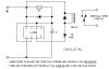
Pin 14 is connected to 24 volts via a 220 ohm resistor and pin 13 to pin 9 and pin 5 to earth this will act as a latching relay if I touch pin 13 to earth and then pin 14.
I want to delay the relay from closing for about 1 to 2 seconds after touching pin 14 and open the instant I touch pin 13.
I there a way of adding a capacitor (and resistor) to allow this and if so what sizes and how?
Thanks,
Bob.
 
Post a schematic of your hookup or at least a link to the data sheet for the relay you are using.

How is this different from your earlier thread?

Can you use a **broken link removed** to reset the relay, and a **broken link removed** to set the relay?
 
Last edited:
relaydrawing.JPG

Is this enough? I don't have data sheets the relays are already in place.
I have used the information and the circuit I was helped with in the previous thread but this is just to help another part of the setup and a capacitor delay would be sufficient.
I have inherited a system that I am learning about all the time. I want to improve it and my ideas are more complex than my knowledge, I have an idea it can be done but am learning how to do it at every puzzle.
 
Last edited:
Can you use a **broken link removed** to reset the relay, and a **broken link removed** to set the relay?
 
not really. I have produced an alteration to the circuit that allows a function when two other relays are closed (the whole circuit consists of about 50 relays) the problem is one is open, and as it closes the other opens, this means that for a moment both are closed and my relay would make. I don't want it to make until the second one closes again, a short delay on my relay would solve this.
I can see I am going to have to show you the whole circuit. :)
I have it on pieces of paper and intend putting it into a circuit diagram program some day.
 
View attachment delay cct.pdf
I think fig 2 would work if I put a relay contact as the switch on with the n/c to earth and the n/o to the 24 volts (with small alterations in component values) and my relay instead of the opto coupler?
but I think there must be an easier way?
Would someone mind pointing out how I could extend the delay, I think it is about 200 millisecs at the moment with these components.
Thanks.
 
Last edited:
If you replace Q1 with an N-FET, and use a CMOS Schmitt circuit between the RC components and the FET gate you could raise the value of R1 considerably to increase the delay to several seconds. A freewheel diode would be needed across the relay coil. Ideally the relay contacts already have a snubber?
 
schmit trigger delay.jpg

Thanks for the reply.

Would this suffice do you think with r2 replaced with a 22k and r3 with a 100 μF capacitor?
I am not familiar with n-fets? do you mean an n channel mosfet and if so which would you recommend? I would prefer the circuit to run from 24 volts.
 
Would this suffice do you think with r2 replaced with a 22k and r3 with a 100 μF capacitor?
The feedback resistor R1 would be discharging the cap. The circuit could be re-configured easily to do the job. A more modern opamp might be better than a '741. Yes, I was referring to an n-channel mosfet. Almost any one would do here, but the bjt shown would be ok if driven by an opamp rather than CMOS.
 
Here is something that might work for you. It is based on either two 555s or one 556 chip.

You specified that the inputs Set~ and Clr~ are active low, such as would happen if you used a clip lead to ground. That is what the switches in the dashed box simulate.

The first 555 is used as a latch (flip-flop). It debounces the inputs and "remembers" that a Set~ pulse has happened, and it starts the delay period of ~2s. When the RC network charges to 2/3 of 12V (8V), the second 555 output goes low, pulling in the load relay. It stays pulled in until the Clr~ pulse goes low.

I made it such that it is the negative going edge of Set~ that starts the timer, and it doesn't matter how wide the Set~ pulse is. It can be very short and end before the 2second delay, or it can even be longer than the 2 second delay period.

Note the traces. The down-edge of the green trace V(set~) starts the 2 second delay. When the blue trace reaches 8V, the purple trace I(L1) shows the current through the relay coil as it pulls-in. When the red trace V(clr~) goes low, that resets the timing network and drops out the relay.

The delay period is proportional to the product of R3 and C1 ( 180000χ10e-6 = 1.8s). You can make it more or less as needed.
 

Attachments

  • DF41a.jpg
    DF41a.jpg
    347.6 KB · Views: 244
Here's the reconfigured post #8 circuit:
DelayedOn.gif
 
Note that the 555 circuit you showed doesn't do what you asked for. You wanted a momentary pulse to latch a relay, and a different pulse to unlatch it. You wanted a delay between the latch pulse and when the relay pulls-in. The circuit you posted will delay the pull-in of a relay, but the power has to be applied for the entire duration of the delay plus however long you want to have the relay be pulled-in.

You would have to add a latching relay ahead of that circuit. The latched relay would have to keep power applied to your posted circuit for the entire duration until a clear pulse unlatches it (two relays, total).

The circuit I posted dispenses with the first (latching) relay. The latching is done intrinsically by the circuit.

btw, Alec's circuit has the same problem...
 
Last edited:
Hi everybody,
I am searching a solution for this question for a long time but this section helps in getting the solution for the problem. Time delaying capacitor is used for discharging onto the coil once the trigger current is off and thanks for the answers given in this section. Use this for future reference https://www.vicky.in/shopping
 

Attachments

  • cart.png
    cart.png
    421 bytes · Views: 173
Last edited:
Yes Mike I am looking for two different circuits for two different reasons :-
1 a circuit that will monitor when a switch has stopped sending signals. This will monitor the wheels of a train pulsing a sensor and energise when the train has passed.

2 a circuit that will energise a relay when two inputs (in series) are on. Passing three sensors, the first goes off, then goes on as the second goes off, when the second goes back on I want my relay to go on. The problem is there could be a very short period in the middle that the first has gone on before the second goes off, I want my relay to ignore that. A train passing three points along the line, this will allow me to let another train enter via a turnout when there is nothing in either section.
I now have circuits that will do both of these things thanks to alec and yourself.
 
Status
Not open for further replies.

Latest threads

Back
Top