Continue to Site

Welcome to our site!

Electro Tech is an online community (with over 170,000 members) who enjoy talking about and building electronic circuits, projects and gadgets. To participate you need to register. Registration is free. Click here to register now.

  • Welcome to our site! Electro Tech is an online community (with over 170,000 members) who enjoy talking about and building electronic circuits, projects and gadgets. To participate you need to register. Registration is free. Click here to register now.

capacitor discharge path help

Status
Not open for further replies.

jonnyjames1985

New Member
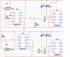
hi was on here about a week ago for help now im back again. could anyone please explain the capacitor discharge path on my diagram, i have to be able to explain it for my project. the top half C1 seems to work with multisim but so does the bottom half C2. the top half and bottom half are seperate circuits working together. any help please
 

Attachments

  • discharge.jpg
    discharge.jpg
    110.1 KB · Views: 248
can anyone explain this

In U1/U2, node 5 is either 0V or Vcc. Assume that node 5 has been at 0V for a long time. Node 3 will have charged to Vcc through R3, which will cause the output of U2 to be low. As node 5 switches from low-to-high, node 3 tries to go to 2*Vcc, but is clamped via D1 to (Vcc+0.65)V. R4 should be moved so that it is series between pin 3 of U1 and node 5, to limit the peak current as U1 switches low-to-high. After the transient dies out, the capacitor such that node 3 is at ~(Vcc+0.5)V, while node 5 is at Vcc.

When U1 switches from high-to-low, node 3 goes to ~gnd, while node 3 is at ~0.5V. This triggers U2, causing its output to go high. Node 3 begins charging toward Vcc, and U2 switches back low when node 3 reaches 2/3Vcc. This puts us back at the initial condition as described above.

U3/U4 works the same as U1/U2 (except for the way U3 is triggered), but R8 is in the correct position to limit the current drawn from the output of U3 (where R4 should have been in the U1/U2 case).
 
Status
Not open for further replies.

Latest threads

New Articles From Microcontroller Tips

Back
Top