Electro Tech is an online community (with over 170,000 members) who enjoy talking about and building electronic circuits, projects and gadgets. To participate you need to register. Registration is free. Click here to register now.
Welcome to our site! Electro Tech is an online community (with over 170,000 members) who enjoy talking about and building electronic circuits, projects and gadgets. To participate you need to register. Registration is free. Click here to register now.
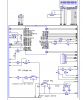
Just applied 24v ac to this circuit and the capacitor C5 went BANG!
C5 is/was 100uf 10v, C5 is 10uf 25v
The 7805 should have output 5vdc but why the BANG!!
Only thing I could think of the 7805 didn't do its job??
That is about the maximum input voltage of the 7805, and well over the voltage of C4, if I have guessed correctly.
Did you connect C5 the right way round?
The input capacitor, C4 should be a lot larger than 10 uF. You need a capacitor that will keep the supply working between mains cycles. 10 uF, even with a 10 V drop, will only support about 10 mA. You would get excessive ripple current in C4, so you should be aiming for 10,000 uF or so, but you could use a much smaller transformer voltage.
Mr. DEB,
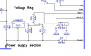
1) Why is your schematic a NEGATIVE image with a BLACK background?
2) Why is it backwards? The input should be on the left side and the output should be .....
3) Didn't you know that the peak voltage of 24VAC is 34V? If you use a 24V center-tapped transformer (with the center-tap connected to 0V) and two rectifier diodes then the output voltage is about +16V.
I had a brain freeze, thats my story and I'm sticking to it.
The transform does not have a center tap.
the diodes are 1n4004.
I simulated using LTSPICE and it came up with 12v output?
Will do futher posts using a positive image.
Already have mounted on pcboard. a simple solution. NOTE I need the 24v ac for the iron heater still.
Off to RS when they open. Don't have and zener diodes but have 3W 300 ohm resistors.
would not the zener provide a better stable voltage to the 7805?
Why does it look clumsy? Need a clean quick solution. Reason for the 7805= a stabile voltage for the PIC
will post entire circuit schematic. This is a PIC controlled soldering iron.
Went with a simple voltage divider.
Changed the cap values
Only get 7v on 7805 output with a 20ma draw. Probably not enough. Need to recheck data sheet for min current draw for regulation.
Changed 7805 and tested with a 300 hm resistor across V=/grd
5v+ instead of 7V .
Reg must have been damaged during cap explosion!!BAM!!
Tested all voltage points.
Going to insert PIC and solder the LCD on tomorrow.
The output of an LM7805 is supposed to be from 4.75V to 5.25V, not 7V. It might be oscillating because it doesn't have a little high frequency 0.22uF or 0.33uF capacitor to ground on its input as shown on its datasheet. It is spec'd with a minimum load current of 5mA.
It works as planed now after I changed out . The one that was in the circuit is the same one that I exploded the cap with.
I have seen data sheets with 1000uf on input as well as .22uf. Have also on the output .1 as well as 10uf.
All depends on how far from source of input as I interpreted the different data sheets.
I am going to add a .1 to output and possibly an additional one ? on input but with a 300 ohm resistor across therails I get 5v
This site uses cookies to help personalise content, tailor your experience and to keep you logged in if you register.
By continuing to use this site, you are consenting to our use of cookies.