Continue to Site

Welcome to our site!

Electro Tech is an online community (with over 170,000 members) who enjoy talking about and building electronic circuits, projects and gadgets. To participate you need to register. Registration is free. Click here to register now.

  • Welcome to our site! Electro Tech is an online community (with over 170,000 members) who enjoy talking about and building electronic circuits, projects and gadgets. To participate you need to register. Registration is free. Click here to register now.

Cascade two identical opamps to double the current output

Status
Not open for further replies.

devonNash

New Member
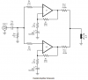
I'm trying to find a cost effective solution.I need to drive a load with over 7A.There are opamps which can handle that sort of current but they are way to expensive (10 times more expensive than 3A output current opamp).So I am trying to design a circuit which can combine the output currents of each opamps together to give me the massive 7A , I need.I have attached the simple circuit which I have developed.The spice simulation of it works perfectly fine.But when I actually implement it,it does not work.Obviously the Opamps and resistors are not identical to each other in the two sets.Because of this output voltages of both opamps are not identical and hence current starts to flow into the output terminals from each other opamps.

So my question is, is there a better way to do this?
 

Attachments

  • opamp adder.JPG
    opamp adder.JPG
    21.4 KB · Views: 248
That is NOT the way to combine the outputs of two or more opamps. I will post an acceptable method later today.
 
You are shorting two outputs together to make smoke.
One might try to make its output at +4.9V and the other might try to make its output +5.1V. Then the 0.2V between them will have the full output current of each opamp in it and in each opamp. Then the opamps will fry fighting each other.
 
Here is the way to increase the peak output current by paralleling opamps.
 
Thanks to you all for the replies.Like audioguru said if the two op amp outputs are different ,their respective output current would sink through each other.This would not happen if the opamp settings are identical.Then they both would have equal output voltages hence block each others current sinking through them.Thats why it works fine in simulation but not in the real world.

I think MikeMl solution is very cool, it tries to balance the two sides with two additional resistors.Thanks Mike for that tip.

cheers to you all.
 
The application sheets for many power amplifier ICs like the LM3886 shows resistors in series with the outputs so they can be paralleled for more output current. Notice the accuracy of the tolerance of the gain-setting resistors (0.1%).
 

Attachments

  • parallel audio power amplifiers.PNG
    parallel audio power amplifiers.PNG
    23 KB · Views: 244
Thanks to you all for the replies.Like audioguru said if the two op amp outputs are different ,their respective output current would sink through each other.This would not happen if the opamp settings are identical.Then they both would have equal output voltages hence block each others current sinking through them.Thats why it works fine in simulation but not in the real world.
If you want to make the simulation look more like the real world, just change one of the gain resistor values by the typical 1% resistor tolerance and then monitor the current output of the two op amps. Your simulation should then show current going out of the op amp output with the highest gain and into the other output.
 
Status
Not open for further replies.

Latest threads

New Articles From Microcontroller Tips

Back
Top