muddasserniaz
New Member
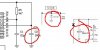
I have built a cd4541 based timer. timing can be changed by setting a dip switch. while the timer is running, oscillator is monitored using Q1 2n7000 and LED (thanks to RON h ).
After selected time the OUTPUT pin 8 is set high by timer. which in turn switches Q2 another 2n7000. and the output (jumper) should be set high.
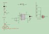
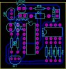
while the timer is working file when built on a veroboard, it is not working on the pcb drawn by proteus (ISIS & ARES).
a) cd4541 oscillator is not working, and wrong voltages appear on PIN 1/2/3.
b) LED1 is continously high.
however when i remove both MOSFETS the timer works and output LED is lit after set time.
i suspect its due to some kind of schematic drawing error (which resulted in a bad PCB being routed by software). plz check MOSFETS connections and placements.
as you can see the Q2 source is not grounded and is connected to an OUTPUT Jumper from which i intend to get out for a small DC motor (100-200 ma current draw.) if this is a problem then how should i ground it and still get get output.
as this is my first schematic and pcb drawn by a software i would like to know if there is any error in it.
the PCB was autorouted.
After selected time the OUTPUT pin 8 is set high by timer. which in turn switches Q2 another 2n7000. and the output (jumper) should be set high.
while the timer is working file when built on a veroboard, it is not working on the pcb drawn by proteus (ISIS & ARES).
a) cd4541 oscillator is not working, and wrong voltages appear on PIN 1/2/3.
b) LED1 is continously high.
however when i remove both MOSFETS the timer works and output LED is lit after set time.
i suspect its due to some kind of schematic drawing error (which resulted in a bad PCB being routed by software). plz check MOSFETS connections and placements.
as you can see the Q2 source is not grounded and is connected to an OUTPUT Jumper from which i intend to get out for a small DC motor (100-200 ma current draw.) if this is a problem then how should i ground it and still get get output.
as this is my first schematic and pcb drawn by a software i would like to know if there is any error in it.
the PCB was autorouted.
 . i plan to include a switch in final pcb.