Continue to Site

Welcome to our site!

Electro Tech is an online community (with over 170,000 members) who enjoy talking about and building electronic circuits, projects and gadgets. To participate you need to register. Registration is free. Click here to register now.

  • Welcome to our site! Electro Tech is an online community (with over 170,000 members) who enjoy talking about and building electronic circuits, projects and gadgets. To participate you need to register. Registration is free. Click here to register now.

circuit for dc voltage output equal to the average volt. of input rectangular wave???

Status
Not open for further replies.

b1pu

New Member
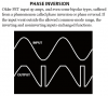
the input and output will be like this...

pic is here...

how can i do this? what will be the circuit? plz help as I do not know much about these ...
 
Last edited:
Your picture is just a little red x on my computer. only certain types can be attached.
 
There is no picture there.
 
The "picture" is not attached here. It is a link from flickr.com that does not exist there.

When I attach an ordinary small PNG file type image then its shows as a red x here instead of as a thumbnail picture. When I click on the red x then the full size picture appears. Here is my attachment:

EDIT: Now it does not show a red x but it also does not show a thumbnail picture.
 

Attachments

  • opamp phase inversion.PNG
    opamp phase inversion.PNG
    15.3 KB · Views: 237
Last edited:
I have added the pic. link, its now working. :)

it wud be great if you help me solve the prob...
 
To design a suitable filter, I would need to know the min/max frequency of the pulse train?

The amplitude of the pulse train?

How much ripple (%, or dB of suppression of the Pulse Frequency) you can tolerate on the filtered output?

What DC supply voltage(s) you have available?
 
Try a low-pass RC filter, which is a series resistor followed by a capacitor to ground. You will probably want to put a unity-gain opamp buffer amplifier before the filter, and maybe after the filter, depending on the rest of the circuit. You might find that you need more filtering, either with additional stages or by using a higher-order active filter. You could download TI.com's Filterpro software for that. I suggest simulating your circuit in LTspice. The filter components' values will depend on how fast you want the output to be able to track changes in the average's value and how smooth you want the output to be, as well as the range of input properties that the circuit needs to handle, such as repetition rate, pulse width, and amplitude.
 
Last edited:
Assuming that the low value is active, all you have to do it put it through a capacitor. They call that PWM.

Very unlikely that a single capacitor will provide sufficient filtering. Let the OP answer my questions....
 
Status
Not open for further replies.

New Articles From Microcontroller Tips

Back
Top