spondootre
Member
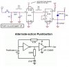
I've copied this circuit and I thought it was supposed to latch on with one press of the switch and off with another. However what I get running it at 12 volts is an output of 12v, then when the sw. is released it instantly drops to 0, if the switch is held on it drops to 0 after a few seconds indicating that the timer part is working fine. Any ideas?? Or is it supposed to do this?!
**broken link removed**
**broken link removed**