Electro Tech is an online community (with over 170,000 members) who enjoy talking about and building electronic circuits, projects and gadgets. To participate you need to register. Registration is free. Click here to register now.
Welcome to our site! Electro Tech is an online community (with over 170,000 members) who enjoy talking about and building electronic circuits, projects and gadgets. To participate you need to register. Registration is free. Click here to register now.
Hi. I typically see a BJT used in an RTL configuration. What about N- or P-channel MOSFET? if not then why. I would think that due to their faster switching time, wouldn't they be better? Thank you.
I would say that RTL is so old that no one bothered to redraw it's equivalent with FETs.
They could be marginally faster, but I don't think they would come close to CMOS process. Also think about the state of development of BJTs vs FETs at that time, so maybe an RTL with FETs would be slower than with BJTs then.
RTL NOR gates work because, in an RTL circuit, BJTs are basically current controlled. MOSFETs are voltage controlled.
If you sum 3 identical resistors into the base of an NPN, current through any one of them can turn on the NPN.
If you sum 3 identical resistors into the gate of an NMOS, a high on only one input will not turn on the NMOS unless you use a high supply voltage, because of the typical threshold voltage of MOSFETs and the voltage divider created by the summing resistors.
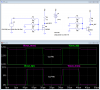
See the attachment. Note that with one input switching, the NMOS circuit does not work with vcc=5V, while the NPN circuit works with either vcc.
Also note that I used devices with typical specs, not worst case. The NMOS circuit might not even work with vcc=10V if worst case Vgs(th) were used.
That's not RTL. The input resistors are redundant. It's NMOS logic.
I realize that an RTL NOR gate using multiple BJTs looks similar, but in it, the resistors are necessary.
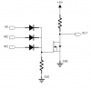
It looks a little like a DTL duck, but it can't quack. The gate has no discharge path to ground (no return current paths for the diodes), and the series resistors are once again redundant.
See attachment for a circuit that will work.
This site uses cookies to help personalise content, tailor your experience and to keep you logged in if you register.
By continuing to use this site, you are consenting to our use of cookies.