Continue to Site

Welcome to our site!

Electro Tech is an online community (with over 170,000 members) who enjoy talking about and building electronic circuits, projects and gadgets. To participate you need to register. Registration is free. Click here to register now.

  • Welcome to our site! Electro Tech is an online community (with over 170,000 members) who enjoy talking about and building electronic circuits, projects and gadgets. To participate you need to register. Registration is free. Click here to register now.

Comparator help

Status
Not open for further replies.

samarsingla

New Member
Hi
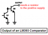
I made a circuit with 393, I have these doubts. First, why is the 10 k resistor there between output and supply. Second, in the circuit I built the output is always coming high. Someone please suggest what could be wrong..
thanx
 
samarsingla said:
I made a circuit with 393
Attach the schematic of your circuit for us to see what is wrong.

why is the 10 k resistor there between output and supply?
Look at the datasheet for the LM393 dual comparator. Its output is an open collector so that two outputs or more can be connected together as an OR gate then a resistor pulls them up.
 

Attachments

  • LM393 output.PNG
    LM393 output.PNG
    6.2 KB · Views: 148
Your sketch doesn't show a connection between the pot at pin 2 and the IC's ground.
What voltage is the battery for the pot?
Your sketch also doesn't show how the photo-diode is connected or how it is powered and if it is connected to the IC's ground.
 
Last edited:
Are you going to update your sketch showing the grounds, the battery's voltage and how the photo-diode is connected and is powered?
 
I dont understand why people don't take a few minutes to make a proper schematic to post instead of using a mspaint picture that no one can read. There are lots of free schematic capture programs out there.
 
FusionITR said:
I dont understand why people don't take a few minutes to make a proper schematic to post instead of using a mspaint picture that no one can read. There are lots of free schematic capture programs out there.
I make all my schematics with MS Paint. I just copy and paste most parts from datasheets and other schematics then make straight lines with the Shift key down.
This schematic is made with MS Paint:
 

Attachments

  • Sound Level Indicator schematic rev1.PNG
    Sound Level Indicator schematic rev1.PNG
    65.7 KB · Views: 149
Status
Not open for further replies.

Latest threads

New Articles From Microcontroller Tips

Back
Top