Continue to Site

Welcome to our site!

Electro Tech is an online community (with over 170,000 members) who enjoy talking about and building electronic circuits, projects and gadgets. To participate you need to register. Registration is free. Click here to register now.

  • Welcome to our site! Electro Tech is an online community (with over 170,000 members) who enjoy talking about and building electronic circuits, projects and gadgets. To participate you need to register. Registration is free. Click here to register now.

Control 2 LED's with seperate logic with one Output

Status
Not open for further replies.

m2cyclone

New Member
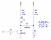
I have a question about how to control 2 LED's with only 1 ground output from a Micro.

I need the ability to turn 1 LED off while I turn on the second LED with the ground output from the Mirco.
Its like a basic blinker circuit, neither LED can be on at the same time.

The output from the control device is Ground with 250mA.

thanks
 
Are you trying to get three states: both off, one on; the other on? That can be done with a bi-color LED and one tristate pin.

Or are you trying to get only two states:One on, the other on.

Is your output pin push-pull, tristate, or open-collector pull-down only.

What is your supply voltage?
 
Last edited:
I'm only going for a two stage, where one LED is on at a time.

The supply voltage is 12v to the LED's, which will be on all the time.
One lamp will be on during normal state.
Then when the micro detects a signal it will turn that lamp off and turn the other one on.

I was trying to think of a way to do this, by tying the output to the ground of on lamp and to the 12v side of the other lamp.
Then when the micro output went to ground it would pull the 12v to ground on one lamp and turn off and the other would turn on since it had a ground signal.

I was thinking in terms of a few resistors and diodes might work for protection between the two circuits.

think something like that would do?
 
Here's a simple circuit than can switch two leds with just one MCU pin. When the pin is high, LED2 is on, when the pin is low, LED1 goes on.

All you need is an extra resistor. The formulas for calculating them is on this webpage:

**broken link removed**

figure_01.gif
 
Last edited:
If it is important that the LEDs run off 12V, you can do it like this.
It's not very efficient, but it's pretty simple.
 

Attachments

  • LED sw.PNG
    LED sw.PNG
    19.3 KB · Views: 217
Here is a circuit that will turn on one LED or the other or no LEDs:


**broken link removed**
 

Attachments

  • Drive2LEDs.gif
    Drive2LEDs.gif
    2.2 KB · Views: 185
Last edited:
Here is my entry into the two LED derby: As long as you use LEDs with different Vf , this circuit relies on having the one with the higher Vf in the D1 position. When the logic pin is low, D2 shunts the current away from D1.
 

Attachments

  • 2Leds.png
    2Leds.png
    30.6 KB · Views: 208
Here is a circuit that will turn on one LED or the other or no LEDs:


**broken link removed**

Colin, what does the open base do?
 
Here is a circuit that will turn on one LED or the other or no LEDs:


**broken link removed**
You might want to indicate where all the loose ends are connected, and how the NPN transistor is going to work in that configuration.:eek:
 
Is the transistor B-E junction supposed to be acting as a zener? If so, that makes a little more sense, but the breakdown voltage of a B-E junction is not specified or controlled by the manufacturer.
 
Last edited:
Status
Not open for further replies.

New Articles From Microcontroller Tips

Back
Top