Hi guys,
Looking for some guidance here, as a project I changed the battery in my sons ride on car to accept my 18v dewalt battery and used a motor speed controller in order to lower the voltage, short story kids ramped it up and there was a bang.
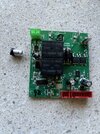
Car stating battery low although it was fully charged, so took out the control board and the capacitor next to the battery input blew apart.
I changed that capacitor and freshened up some of the solder around, and installed an 18v to 12v step down this time, but it still won’t work states battery low, I checked voltage at connection it’s 12v I’m at a loss here board looks fine to me.
I did order a new control board but would still like to work out what else could of went wrong, Any help would be appreciated
Looking for some guidance here, as a project I changed the battery in my sons ride on car to accept my 18v dewalt battery and used a motor speed controller in order to lower the voltage, short story kids ramped it up and there was a bang.
Car stating battery low although it was fully charged, so took out the control board and the capacitor next to the battery input blew apart.
I changed that capacitor and freshened up some of the solder around, and installed an 18v to 12v step down this time, but it still won’t work states battery low, I checked voltage at connection it’s 12v I’m at a loss here board looks fine to me.
I did order a new control board but would still like to work out what else could of went wrong, Any help would be appreciated