hello,
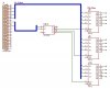
i am trying to control devices via parallel port, in Attachment the circuit diagram, devices will be connect to 3 flip flops.
assume that i want to switch ON the first device in the first flip flop, so the [0 - 3] data bus = 1000 and decoder input = 01 then 00 to generate puls to the flip flop.
now if i want to switch ON the second device the [0-3] data bus = 1100 and so on.
is this the correct method?
is there any more efficient design?
thanks.
Attachments
Last edited:
")
