chrisdagger
New Member
Hello all!
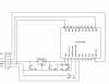
I seem to be having a little trouble with an oscillator on a PIC chip. What is happening, is when there is high current draw, the oscillator slows down, significantly. I have the crystal configured with 2x 15pF capacitors, and have also tried with a 10M resistor in the circuit, but don't seem to be able to keep it steady. The PCB I've made is connected to an external device, and so I have little control over it's current draw!
Is this pretty normal for crystal oscillators? The stability of the oscillator is given as +/- 50ppm. I also have a very similar result using a ceramic resonator.
I have uploaded a video to the interweb in MP4 format - www.arcadeangel.co.uk/MOV00008.MP4 . In the video, you can see where the external device is drawing current, first of all when it is running stepper motors, and secondly (when the waveform is really sketchy) when there is a lot of illumination.
And I will always maintain that an oscilloscope is the second most important piece of equipment in any workshop after the coffee maker. ;-)
Any advice would be greatly appreciated!
")