Continue to Site

Welcome to our site!

Electro Tech is an online community (with over 170,000 members) who enjoy talking about and building electronic circuits, projects and gadgets. To participate you need to register. Registration is free. Click here to register now.

  • Welcome to our site! Electro Tech is an online community (with over 170,000 members) who enjoy talking about and building electronic circuits, projects and gadgets. To participate you need to register. Registration is free. Click here to register now.

Current limiting (2-5ma) help

Status
Not open for further replies.

swapnil14327

New Member
Hi,
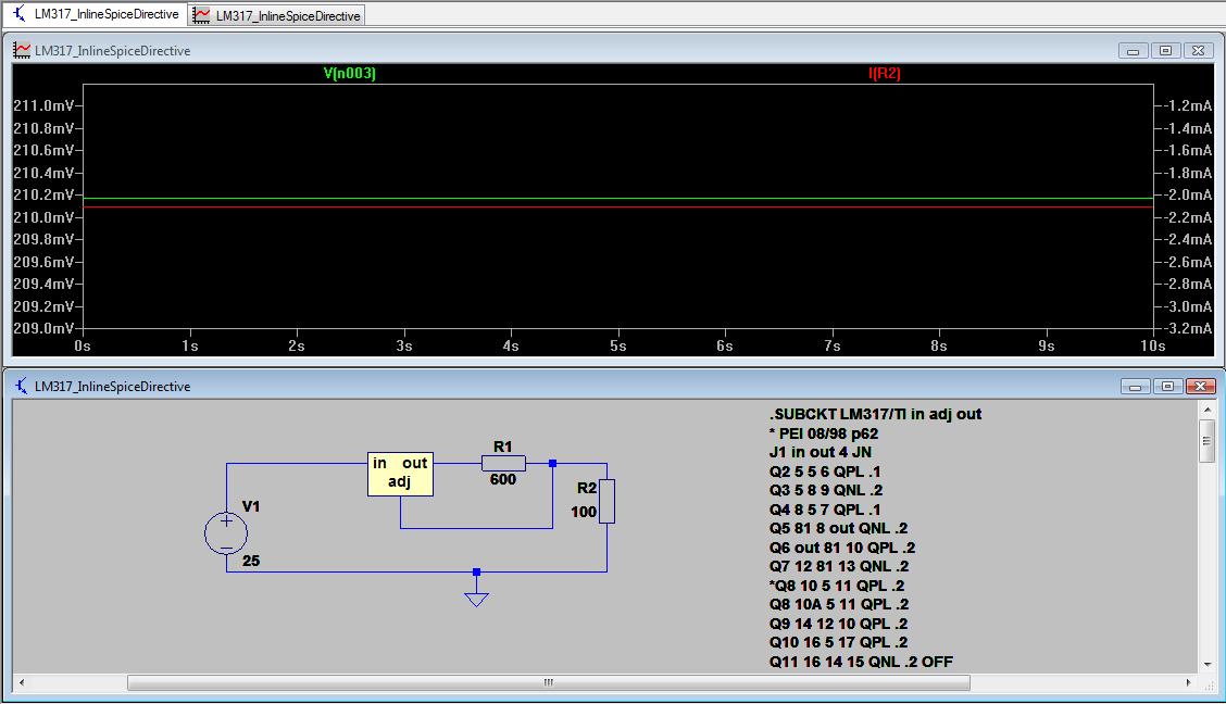
I have a device which requires very low current (2-5mA) and 20V.

I tried with LM317 using but, but I am not able to get the require voltage.
I also tried with JFET but still i am not able to get the voltage..

My device's output impedance is "100 ohm"

when i connect the 100 ohm resistor as load to the LM317 or JFET circuit , i am able to get voltage in mili volts.

my input ratings are Vin = 25V / 200mA
and i want Vout = 20V / 2~5mA

in less cost..

i have heard about current regulating/limiting diodes but they are too costly.

can any one help me please..

lm317_current_limit-jpg.80873
 

Attachments

  • lm317_current_limit.jpg
    lm317_current_limit.jpg
    84.4 KB · Views: 2,124
hi and welcome.
With a constant current source of 2mA to 5mA, into a 100R load its not possible to get 20V across the 100R.

What is the type of 100R load, ie: what is the 20V at 5mA for.?:)
E
 
hi and welcome.
With a constant current source of 2mA to 5mA, into a 100R load its not possible to get 20V across the 100R.

What is the type of 100R load, ie: what is the 20V at 5mA for.?:)
E

i need the 20V and 2-5mA for a sensor. its an accelorometer sensor,
its ratings are 18-30V / 2-5mA
 
Why is the device's output impedance relevant? Surely all you are interested in is its supply voltage and supply current draw?
Why do you want a current limiter? The accelerometer will draw whatever current it needs.

Edit:
Minimum load current for an LM317 can be as much as 5mA, so additional loading may be needed.
 
Last edited:
the "100 ohm" resistance is my load where the sensor will be connected(its sensors impedance i used in simulation)..

and the ratings of the sensor is 2-20mA more than that will destroy the sensor..
the sensor itself is very costly so i am trying for 2-5mA ratings.

is there any other device other than LM317.
 
i need the 20V and 2-5mA for a sensor. its an accelorometer sensor,
its ratings are 18-30V / 2-5mA

hi,
I would use a JFET for the constant current, much more stable than a LM317.

Can you post the model number/type for the accelerometer ? we can check it out.
E
 
i need the 20V and 2-5mA for a sensor. its an accelerometer sensor,
its ratings are 18-30V / 2-5mA

All that means is the required voltage is 18-30V. The sensor will draw 2-5mA at whatever voltage you supply.

You could attach this sensor to a 22V 100A power supply, and the sensor would still only draw 2-5mA. Providing of course the supply could regulate with such a small load. Which of course appears to be the issue with the LM317. It has a minimum load of 5mA, so if you get a good sensor that only draws 2mA, the LM317 will not be able to regulate the voltage well.

The simplest way would be to setup the LM317 with 20V out and connect the sensor in parallel with a 1/2W 4K ohm resistor (20V @ 5mA is 0.1W). The resistor will guarantee the 5mA minimum load and the sensor will draw what it needs. The LM317 will supply 20V with a load of up to 10mA or power output of 0.2W.
 
All that means is the required voltage is 18-30V. The sensor will draw 2-5mA at whatever voltage you supply.
My point exactly. I don't believe you need a controlled current source; unless you have a very unusual sensor. As Eric says, can you post the accelerometer type/model info?
 
[3] DO NOT APPLY POWER TO THIS DEVICE WITHOUT CURRENT LIMITING, 20 mA MAX. TO DO SO WILL DESTROY THE INTEGRAL IC AMPLIFIER
I concede, you do need a current-limited source :)
 
All that means is the required voltage is 18-30V. The sensor will draw 2-5mA at whatever voltage you supply.

Hi,
Do NOT connect directly to a +Vsupply, it will be damaged.!

Construct a 5mA or 10mA Current LIMITED source say at 20V

E
 

Attachments

  • AAesp01.gif
    AAesp01.gif
    8.3 KB · Views: 407
yes..
that's what i am telling..
the sensor itself is very costly, i cant risk to connect it to supply..

can you please suggest me with some design so that i get the max of 5mA current with atleast 20V .
even if my circuit accidentally gets shorted with ground, I want the current restrected with 5mA only.
 
Here's one way:-
CurrentLimiter.gif

The graphs show the current limit for a V1 range of 23-30V and a temperature range of 10C-50 C.
Increase R3 to reduce the current limit.
R1,C1 limit any supply spike but may not be needed.
 
Hi,

I also tried with JFET.
as i connect load 100ohm it gives me 240mA
so not able to connect with the JFET also..

please suggest me some design for this..

using the LM317 and/or JFET circuit, am i on right track for "Dytran 3225F" ?


jfet-current-limiter.jpg
 
Your sensor is NOT a 100 Ohm load. It gives an output of 10mV/G and has a 100 Ohm output impedance.
(It's a pity the datasheet doesn't include an application example showing the power supply arrangement).
please suggest me some design for this.
See post #13.
 
Last edited:
thanks for the design Alec.

the output impedance of sensor is "100 ohm" just for simulation i am using it as load.

am i right..? what should i use as a sensor here.?
in your above design as a sensor (the resistor) what value have u taken for it?
 
the output impedance of sensor is "100 ohm" just for simulation i am using it as load. am i right..?
No. If the sensor draws 20mA from a 30V supply it is acting as a 1.5k load, which is the value I used in the sim.
Here's the .asc file
 

Attachments

  • CurrentLimiter.asc
    1.4 KB · Views: 222
NIL.

Here is a circuit I have seen used with similar accelerometers. I think I saw it on some application note, long ago.

This circuit simultaneously biases the accelerometer to operate with constant current through it; the acceleration modulates the effective resistance of the accelerometer and the opamp converts that to a buffered output voltage.

Note that by selecting the voltage at the non-inverting input of the opamp (1V in this example), and by picking R2, you can set the current through the accelerometer.
In my example, I choose 10mA (1V/100 Ohm). For the simulation, I vary the effective resistance of the accelerometer to see if the current remains constant, and to see the effect on the opamp's output voltage...

In the second simulation (time domain), I added a soft-start capacitor and plotted the current through the accelerometer at three different values of accelerator resistance (500, 1K, and 1.5K) as the power is first turn on. Note that the current comes up nicely controlled.
 

Attachments

  • DF82.jpg
    DF82.jpg
    117.3 KB · Views: 371
  • DF82a.jpg
    DF82a.jpg
    105.1 KB · Views: 360
Last edited:
Status
Not open for further replies.

Latest threads

Back
Top