Continue to Site

Welcome to our site!

Electro Tech is an online community (with over 170,000 members) who enjoy talking about and building electronic circuits, projects and gadgets. To participate you need to register. Registration is free. Click here to register now.

  • Welcome to our site! Electro Tech is an online community (with over 170,000 members) who enjoy talking about and building electronic circuits, projects and gadgets. To participate you need to register. Registration is free. Click here to register now.

DC Motor Control Circuit

Status
Not open for further replies.

ElectroMaster

Administrator
Here, S1 and S2 are normally open , push to close, press button switches. The diodes can be red or green and are there only to indicate direction. You may need to alter the TIP31 transistors depending on the motor being used. Remember, running under load draws more current. This circuit was built to operate a small motor used for opening and closing a pair of curtains. As an advantage over automatic closing and opening systems, you have control of how much, or how little light to let into a room. The four diodes surriunding the motor, are back EMF diodes. They are chosen to suit the motor. For a 12V motor drawing 1amp under load, I use 1N4001 diodes.
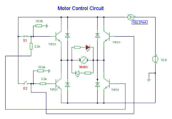
dc_motor_control_circuit.gif
 
if wish to control motor speed using pwm?

i wish to control motor speed by trigger the BJT/mosfet(i m using mosfet in my project). The output voltage(between motor) i get wont come out as my expected(not a rectangular waveform) and got a lot of distortion. Average value of my Vout is higher much than expected, let say pwm duty cycle is 10%, average voltage i get is 40-50%. Why this problem occur? Can give me a solution or suggestion?
 
sorry if i m mistaken but i u r using a mechanical 'push' button... then wats the need of those free wheeling diodes,resistors, etc?
 
You should use a single SPDT switch in place of S1 and S2. This will prevent the circuit from burning out if both S1 and S2 are closed simultaneously.
 
Couple of problems with this design

1) the LED's around the motor.
Since they are in anti-parallel it will ensure an LED will light up depending on th evoltage flow

BUT in doing so you have provided a clamp across the motor, a clamp of 1.2V as a rule of thumb with LED's

The speed of a brushed-DC is proportional to the voltage at the terminals


2) inadquate gate-drive
 
akg said:
Styx said:
BUT in doing so you have provided a clamp across the motor, a clamp of 1.2V as a rule of thumb with LED's
The speed of a brushed-DC is proportional to the voltage at the terminals
No problem . there is a resistor in b/w the led and motor .

Very true, but then you set that burn-resistor to drop a certain potontial;

Say you set it for the DC-link at 12V so the burn-resistor drops 10.8V. THAT is only good IF you go into over-modulation or 100% PWM

Less and the brightness drops


Say you set it for a lower voltage, IF you over-drive it then you will burn it out.

BEst bet would be to have the LED hanging off the gate signal instead
 
Styx said:
Very true, but then you set that burn-resistor to drop a certain potontial;
Say you set it for the DC-link at 12V so the burn-resistor drops 10.8V. THAT is only good IF you go into over-modulation or 100% PWM
Less and the brightness drops
Say you set it for a lower voltage, IF you over-drive it then you will burn it out.
BEst bet would be to have the LED hanging off the gate signal instead
Ok..I agree..
 
errr saturday morning, brain kicking in, IF the LED's were hung of the gate-signal they would be provided with a PWM and thus they would dim with lower PWM.

so looks like no matter where you put the LED's they will dim with low duty, unless you made a FWD/REV signal
 
Another problem with this circuit is the top two transistors are configured as emitter followers so they never fully saturate and you don't get any voltage amplification either. If you shift the components about a bit you can swap them for PNP transistors like TIP32s which will sove this problem.

Another thing, what happens if the user presses both S1 and S2?

There needs to be some sort of interlock to prevent this - a few logic gates might do.
 
if i may add to this post i would like to say that my learning expereince is that im still learning ..so dont think im a know it all it's just i noticed how you all where discussing the l.e.d. subject on the schematic at the begginig...
if you remove the led's and add a duel singal throw switch and add the l.e.d's and the requiered voltage to one side of the switch as to indicate dirrection then the problem with clamping would be overcome don't you think?
 
I have a 3 horsepower 110vDC motor from a treadmill machine. That will likely require some very stout components to operate it!
 
HiTech said:
I have a 3 horsepower 110vDC motor from a treadmill machine. That will likely require some very stout components to operate it!

That is exactly what they are for. Normal consumer grade stuff uses 1-2HP. The PWMs that drive it use 50A IGBTs, though the continuous current is limited to 15-25A depending on the unit.

D.
 
ElectroMaster said:
Here, S1 and S2 are normally open , push to close, press button switches. The diodes can be red or green and are there only to indicate direction. You may need to alter the TIP31 transistors depending on the motor being used. Remember, running under load draws more current. This circuit was built to operate a small motor used for opening and closing a pair of curtains. As an advantage over automatic closing and opening systems, you have control of how much, or how little light to let into a room. The four diodes surriunding the motor, are back EMF diodes. They are chosen to suit the motor. For a 12V motor drawing 1amp under load, I use 1N4001 diodes.

dc_motor_control_circuit.gif

You should just put the two LEDs anti parallel, as it stands you are breaking the unlit one down. They typically have a 5V reverse breakdown rating.

And you need to change the 1N4001s to schottkys. 1N4001s are slow diodes that are not worth anything far beyond line frequency.

D.
 
hey its really nice to be a member...
can you help to build an driver of the step motor (8 coils), to control the direction of torque if the motor
 
Status
Not open for further replies.

Latest threads

New Articles From Microcontroller Tips

Back
Top