Hi
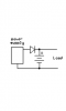
I want to design a simple DC UPS circuit that will also charge a 12V SLA battery. The attached drawing shows the circuit that I require help with.
The load resistor RL represents the device load (draws 6 amps max typically only 2 amps).
My understanding of the circuit is that when the 14.2V power supply (actually an AC/DC power source) is present the voltage to the load will be approximately 13.8V to account for the voltage drop of the diode. With 14.2V present the battery will be charged to a max of 13.8V.
When the AC goes off the battery will switch in and supply VB minus the drop of the diode to the load.
I am not positive on the function of RB but I thought it would control the max current the battery receives while charging. The current charging the battery will decrease as its voltage approaches 13.8V and I believe this is a function of (VB-13.8)/RB where VB is the voltage of the battery while charging.
I built the circuit with RB=1 ohm and measured the voltage across battery terminals and current to battery while charging. The current measured much higher (2 to 3 times) than I anticipated per my assumption above.
Does anyone have a simple explanation or a simple circuit that will do the same.
 hm: resistor [you say] and Icharge of 2.2A amps wouldn't give you a battery voltage of 13.2V???