Continue to Site

Welcome to our site!

Electro Tech is an online community (with over 170,000 members) who enjoy talking about and building electronic circuits, projects and gadgets. To participate you need to register. Registration is free. Click here to register now.

  • Welcome to our site! Electro Tech is an online community (with over 170,000 members) who enjoy talking about and building electronic circuits, projects and gadgets. To participate you need to register. Registration is free. Click here to register now.

decoupling capacitor to pic16f877

Status
Not open for further replies.

raviram87

New Member
i had a doubt on connecting the decoupling capacitor in my pic16f877...

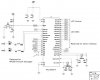
the pic16f877 has Vdd to pins 1, 11 and 32.
and Vss to pins 12 and 31.

i have connected a 0.1uF capacitor between pins 1 and 12.

is this the right way of doing it?

or should each Vdd pin be connected through a 0.1uF capcitor?
 
Hi

You should ideally put a 100nf capacitor across pins 32 + and pin 31 -, and another 100nf across pin 11 + and pin 12 - although you can usually make do with just one if your power rails are straight across from 32 to 11.

Pin 1 is Mclre and should not be connected directly to +5v, but by a 10k resistor, a decoupling capacitor in not needed here, unless you are using a reset switch etc.

HTH
 
its helpful , and recommended to connect 100nf decoupling capacitors between +VCC & GND .

that cancel the effect of electronic noise , so the PIC16f877 has a high sensitivity for the noise .

but if u built an 5V DC PSU , its very simple , its consist of 470UF on the input of the 7805 and 100 UF and 100NF on the output of 7805 , this will help u , and i' m work on this way , and i don' t have a problems .
 
thanks for your replies...

i have attached a picture... the picture shows the PIC16f877 used for some home automation...

though i am using the PIC for a completely different purpose, i am just looking at the way in which the 0.1uF capacitors have been connected to the Vdd pins...

can i use the same way of connecting the capcitors?
 

Attachments

  • image012.jpg
    image012.jpg
    32.1 KB · Views: 7,192
???
They're are two 0.1uf caps in the drawing, they need to be near the power / gnd pairs on the 16F877A. It's assumed the reader will follow good PCB layout practice. Just like the crystal and its caps, you would mount thoses as near as possible to the xtal pins.
 
Status
Not open for further replies.

Latest threads

New Articles From Microcontroller Tips

Back
Top