fantabulous68
Member
SPECIFICATIONS:
*PWM OUTPUT VOLTAGE OV (OFF) OR 5V (ON) WITH A MAX CURRENT CAPABILITY OF 0.1ma
*A constant pulse frequency of 100KHz(each phase is 50KHz)
*Accepts an input voltage of -5V.....+5V to create a duty cycle range D=0.0 to D=1.0
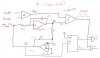
I want to know if i designed the components of the triangle wave generator correctly ie. R1, R2, R3 and the capacitor
(see diagram)
R1 & R2 will have the same current right?
therefore
choose R1=20K & R2=10K
so current in R1 & R2= 500uA
to solve the capacitor
each phase is 50KHz therefore Ton=20uS
*PWM OUTPUT VOLTAGE OV (OFF) OR 5V (ON) WITH A MAX CURRENT CAPABILITY OF 0.1ma
*A constant pulse frequency of 100KHz(each phase is 50KHz)
*Accepts an input voltage of -5V.....+5V to create a duty cycle range D=0.0 to D=1.0
I want to know if i designed the components of the triangle wave generator correctly ie. R1, R2, R3 and the capacitor
(see diagram)
R1 & R2 will have the same current right?
therefore
current of R2 and R1 = pwm output voltage / R2 = input voltage / R1
= 5V/R2 = 10V/R1
choose R1=20K & R2=10K
so current in R1 & R2= 500uA
R3 = pwm output voltage/MAX CURRENT CAPABILITY = 5V / 0.1mA=50K
to solve the capacitor
T=Ton= R1 X C
each phase is 50KHz therefore Ton=20uS
C=20uS / 50K = 400pF