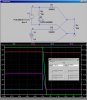
Hello everyone, I'm doing a project and could use some advice or help, I'm trying to designed a 9 V backup battery with a 9 V primary source coming in.
I'm trying to design it so that when the primary source gets disconnected or turns off the backup battery will power the rest of the circuit. I'm having troubles as well with the LED's because the first LED works as it should but the second LED showing that the backup battery has taken over doesn't illuminate properly.
Any help would be greatly appreciated.