Continue to Site

Welcome to our site!

Electro Tech is an online community (with over 170,000 members) who enjoy talking about and building electronic circuits, projects and gadgets. To participate you need to register. Registration is free. Click here to register now.

  • Welcome to our site! Electro Tech is an online community (with over 170,000 members) who enjoy talking about and building electronic circuits, projects and gadgets. To participate you need to register. Registration is free. Click here to register now.

discrete power dif amp

Status
Not open for further replies.

vlad777

Member
**broken link removed**

Hello.

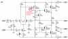
I made this amp from salvaged parts from PC monitor and PC PSU.
Beleve or not it works even though I didn't bias input.
Bass is good and it has power but distorsion is notisable.
I am hoping to stabilize q point just by two resistor feedback.

So how can I make it better?

Many thanks!


Edit: Sorry power is +30V -30V.
 
Last edited:
Hi. Try following:

Remove 10k resistor in feedback loop. This one reduce the feedback, and effect should be faster voltage shift when output voltage swings around ground.

On real amplifiers you'll have resistors between output transistors that ensure a smooth transition when conducting transistor change.
 
The output transistors have no bias voltage so the crossover distortion will be horrible even when it has lots of negative feedback with a gain of only 1.
Nobody makes a class-B audio amplifier.

The circuit does not have a frequency compensation capacitor so it will probably oscillate with more negative feedback.
 
Yes I know it's a constant current source but I got confused how will the voltage change if
current is constant.
Why is this better then just R?
Slightly more linear compared to a similar amplifier with just a resistor instead. It also keep the bias voltage between the gates constant.
 
Yes I know it's a constant current source but I got confused how will the voltage change if
current is constant.
Why is this better then just R?

I don't know why you suddenly leaped from a bipolar amp to an FET one, but for the bipolar one it's vitally important in order to provide sufficient drive on that polarity output (or you can bootstrap it with a capacitor).
 
The BFQ252 PNP transistor is a high voltage, low current video transistor. Since your amplifier has negative feedback but has no frequency compensation capacitor then the amplifier is probably oscillating at a high frequency that kills the first transistor in your compound pair.
 
Audioguru can you please tell me where this cap should go?

Is it millers cap between base and collector (of q7 equivalent on my sch) ,or cap between out and gnd ,or cap over resistor from out to inverting input?
 
Last edited:
Audioguru can you please tell me where this cap should go?

Is it millers cap between base and collector (of q7 equivalent on my sch) ,or cap between out and gnd ,or cap over resistor from out to inverting input?
There are hundreds of amplifier schematics on the internet. Here is a good one that is similar to yours and it has a frequency compensation capacitor to keep it from oscillating.
 

Attachments

  • good amplifier.PNG
    good amplifier.PNG
    20.3 KB · Views: 187
Status
Not open for further replies.

Latest threads

New Articles From Microcontroller Tips

Back
Top